Die surface inspection
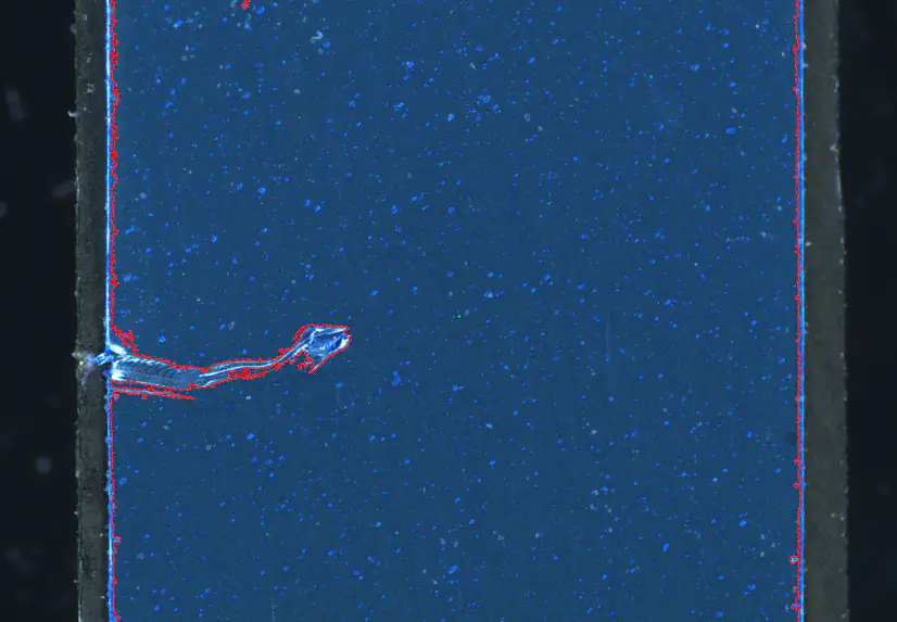
Inspect defined die regions for chipping, scratches, particles and contamination. Connect the inspection result to the part position and strip map.

Inspection, measurement and automation built around what your production needs to see.
Explore application examples from Axmatic’s work, from fine surface details to the way parts move through a line.
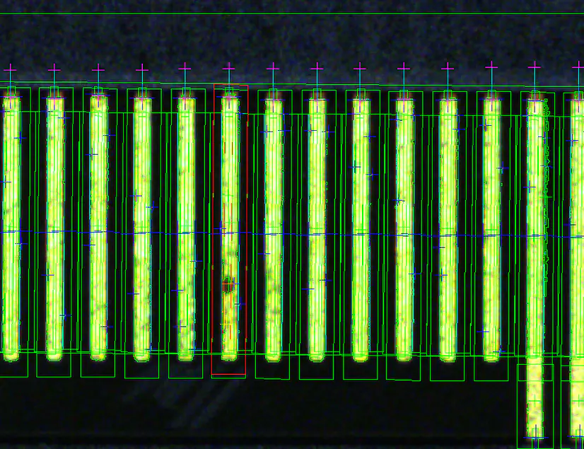
Inspect fine surface details, wire connections and package features with views and criteria matched to the part.
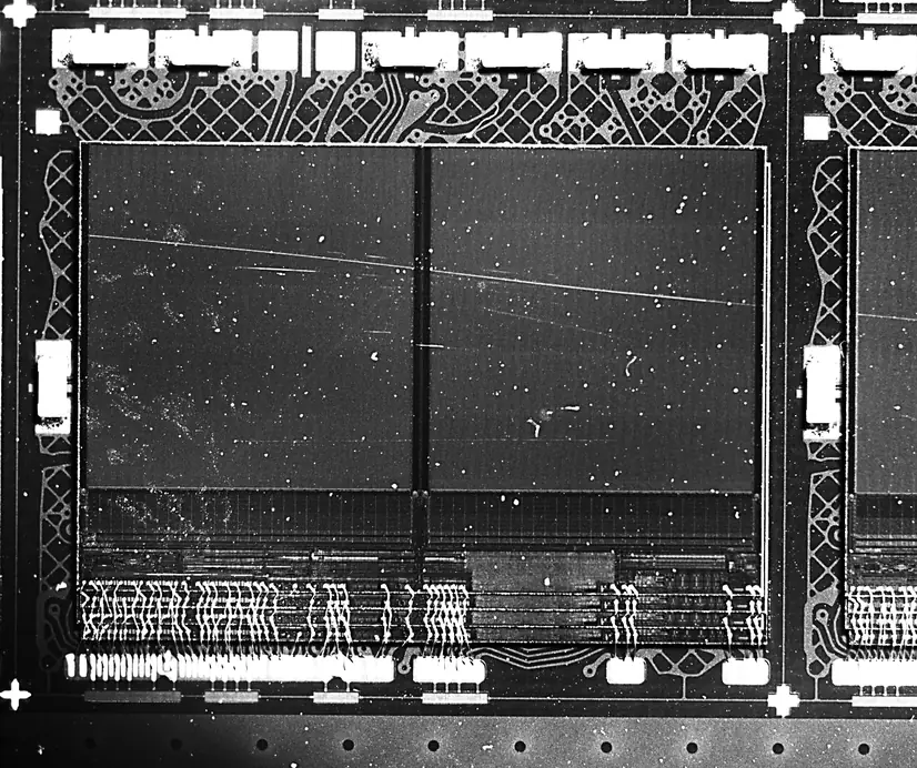
Inspect defined die regions for chipping, scratches, particles and contamination. Connect the inspection result to the part position and strip map.
Check wire presence, breaks, shifts and shorted wires, together with bonding-ball position and visible size. Inspection criteria follow the part and optical arrangement.
Inspect package markings and lead features using application-specific views. The part presentation and acceptance criteria define the inspection setup.
Use magnified images and lighting choices to review small cracks, dents, stains or foreign material. Operator viewing and assisted part handling can support the workflow.
A flex assembly brings different materials and features into one view. Inspection rules and illumination follow the region being checked.
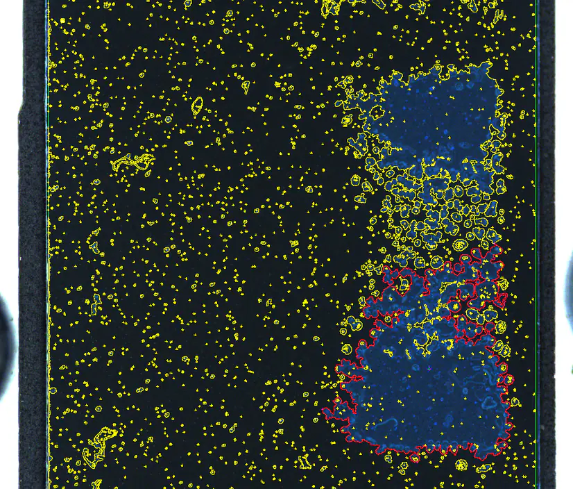
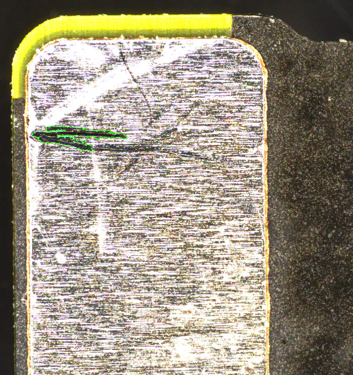
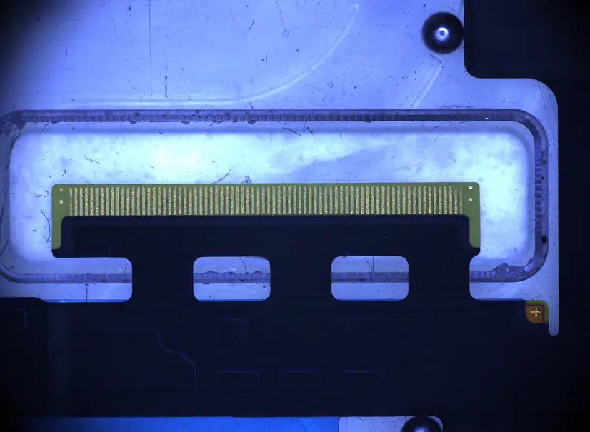
Inspect contact and connector regions for breaks, discoloration, contamination and visible damage. Use region-specific checks across the assembly.
Inspect transparent epoxy for wrinkles, overlap, missing material and foreign objects. Develop the view around the material’s contrast and the defect to be seen.
Review adhesive film for air bubbles, contamination and missing adhesive. Position and material appearance form part of the inspection criteria.
Check assembly regions for stray solder, exposed copper, excess glue, dents and burrs. Combine the relevant checks around each part feature.
Inspect SUS parts for scratches, deformation, contamination and displacement. Match the optical view to the surface and its reference features.
Check liners and adhesive tape for cracks, scratches, shifts and press marks. Tape-format inspection can also connect the image to controlled material movement.
Set up image-based measurements around part geometry, positioning references and the way the material is presented.
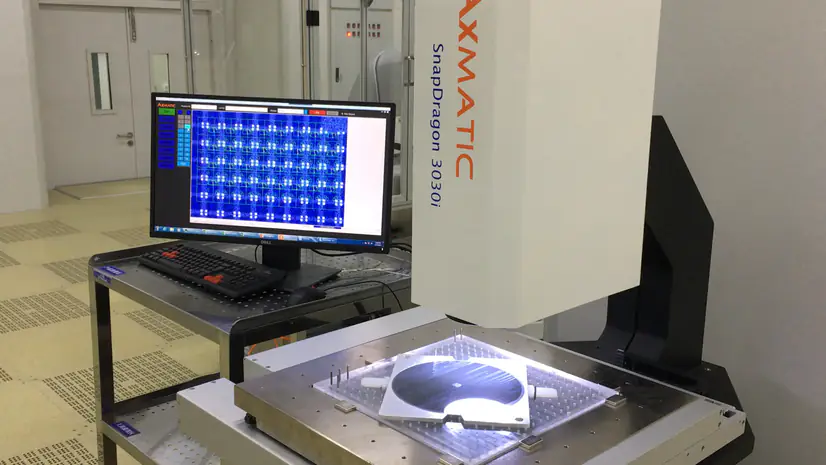
Measure multiple gold-finger features with image-based routines. Part positioning, optical selection and the measurement program work together.
Assess contours and feature positions on flex parts, including wearable-electronics examples. Stored measurement routines support repeated checks of the selected features.
Measure die X/Y offsets and rotation against part and strip references. Relate the measurements to the inspection result and material map.
Explore image-based inspection and measurement with wafer presentation matched to the task. Define the inspection views, positioning and feature coverage around the application.
Application example
Die-placement and optical-reference views support the documented lens-attach measurement examples. Discuss the features, optics and fixturing for a comparable alignment task.
Gold-surface assessment and spectral imaging address different aspects of what a material reveals. Define the inspection region and the information the application needs.
Assess selected gold-surface regions and review coverage maps, overlays and application-defined grading. Reference regions and inspection criteria provide the context for the result.
Combine spatial and spectral information to explore differences in materials and surface conditions. Camera, illumination and analysis choices follow the application.
Coordinate inspection with trays, strips and tape. The result needs to stay connected to the material as it is loaded, positioned, sorted or rechecked.
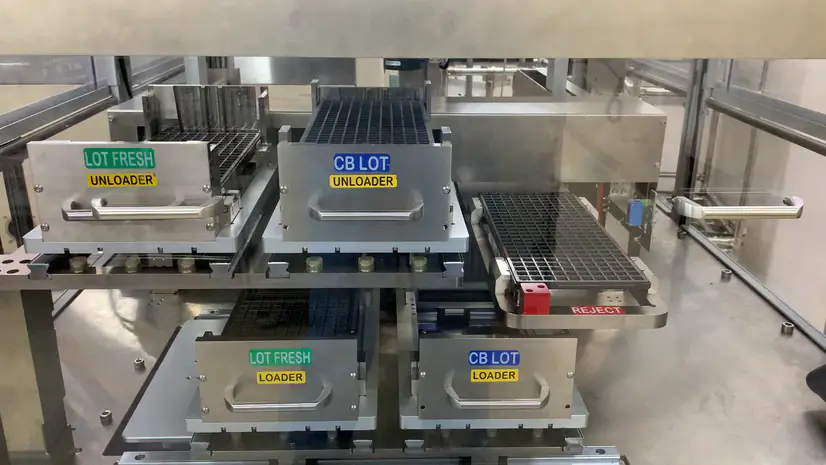
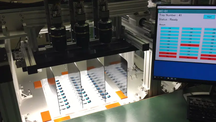
Check tray quantities and relate pocket maps to production data. Particle rechecks and reinspection can form part of the handling workflow.
Coordinate lot combination and replacement of missing units within the tray workflow. Keep the source, destination and unit quantities connected to the process.
Connect ACF curl, deformation and warpage checks with robotic reject replacement. The part, inspection arrangement and handling sequence define the configuration.
Combine inline height and visual checks with sorting and stacking. Position the inspection within the flow of material through the process.
Count tape-fed parts and combine vision inspection with motorised handling. Inspection views and material presentation follow the tape and part format.
Check printed information and compare outgoing material with the expected data. Inspection feedback helps the operator review mismatches in the workflow.
AN OUTGOING VERIFICATION WORKFLOW
Check the placement and visible condition of printed and 2D marks. Use the part reference and application criteria to assess the mark.
Assess code quality alongside whether the code can be decoded. Source examples illustrate grading differences and the need to define the acceptance method for the application.
Compare box-label and shipment data, with quantity checks and mismatches routed for review. Connect the camera view with the expected server-side information.
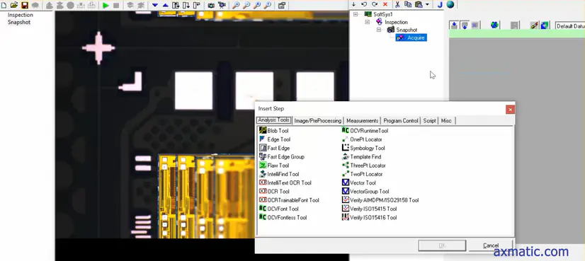
We develop software for customers. Machine-operation examples connect the inspection setup, the material being handled and the information your team needs.
Tell us about the part, the feature or defect, your acceptance criteria and how the material moves. We’ll discuss the application around your process.