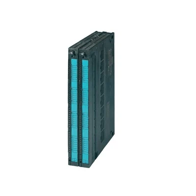
The FM 455 closed-loop control module is the intelligent 16-channel closed-loop control module for universal closed-loop control tasks.
| Article number | 6ES7455-1VS00-0AE0 |
| SIMATIC S7-400, CONTROL MODULE | |
| Supply voltage | |
| Load voltage L+ | |
| ● Rated value (DC) | 24 V |
| ● permissible range, lower limit (DC) | 20.4 V |
| ● permissible range, upper limit (DC) | 28.8 V |
| Input current | |
| from load voltage L+ (without load), max. | 400 mA; typ. 330 mA |
| Power loss | |
| Power loss, typ. | 10.7 W |
| Power loss, max. | 16.2 W |
| Digital inputs | |
| Number of digital inputs | 16 |
| Input characteristic curve in accordance with IEC 61131, type 2 | Yes |
| Input voltage | |
| ● Rated value (DC) | 24 V |
| ● for signal “0” | -3 to +5V |
| ● for signal “1” | 13 to 30V |
| Input current | |
| ● for signal “1”, typ. | 7 mA |
| Cable length | |
| ● shielded, max. | 1 000 m |
| ● unshielded, max. | 600 m |
| Digital outputs | |
| Number of digital outputs | 32 |
| Short-circuit protection | Yes; Electronic |
| Limitation of inductive shutdown voltage to | L+ (-1.5 V) |
| Controlling a digital input | Yes |
| Switching capacity of the outputs | |
| ● on lamp load, max. | 5 W |
| Load resistance range | |
| ● lower limit | 240 Ω |
| ● upper limit | 4 kΩ |
| Output voltage | |
| ● for signal “1”, min. | L+ (-2.5 V) |
| Output current | |
| ● for signal “1” rated value | 0.1 A |
| ● for signal “1” permissible range for 0 to 60 °C, min. | 5 mA |
| ● for signal “1” permissible range for 0 to 60 °C, max. | 150 mA |
| ● for signal “0” residual current, max. | 0.5 mA |
| Parallel switching of two outputs | |
| ● for logic links | Yes |
| Switching frequency | |
| ● with resistive load, max. | 100 Hz |
| ● with inductive load, max. | 0.5 Hz |
| ● on lamp load, max. | 100 Hz |
| Cable length | |
| ● shielded, max. | 1 000 m |
| ● unshielded, max. | 600 m |
| Analog inputs | |
| Number of analog inputs | 16; With thermocouples or 2-wire connection; 8 with Pt 100 or 4-wire connection |
| permissible input voltage for voltage input (destruction limit), max. | 20 V |
| permissible input current for current input (destruction limit), max. | 40 mA |
| Input ranges | |
| ● Voltage | Yes |
| ● Current | Yes |
| ● Thermocouple | Yes |
| ● Resistance thermometer | Yes |
| Input ranges (rated values), voltages | |
| ● 0 to +10 V | Yes |
| — Input resistance (0 to 10 V) | 100 kΩ |
| ● -1.75 V to +11.75 V | Yes |
| — Input resistance (-1.75 V to +11.75 V) | 100 kΩ |
| ● -80 mV to +80 mV | Yes |
| — Input resistance (-80 mV to +80 mV) | 10 MΩ |
| Input ranges (rated values), currents | |
| ● 0 to 20 mA | Yes |
| — Input resistance (0 to 20 mA) | 50 Ω |
| ● 0 to 23.5 mA | Yes |
| — Input resistance (0 to 23.5 mA) | 50 Ω |
| ● -3.5 mA to +23.5 mA | Yes |
| — Input resistance (-3.5 mA to +23.5 mA) | 50 Ω |
| ● 4 mA to 20 mA | Yes |
| — Input resistance (4 mA to 20 mA) | 50 Ω |
| Input ranges (rated values), thermocouples | |
| ● Type B | Yes |
| — Input resistance (Type B) | 10 MΩ |
| ● Type J | Yes |
| — Input resistance (type J) | 10 MΩ |
| ● Type K | Yes |
| — Input resistance (Type K) | 10 MΩ |
| ● Type R | Yes |
| — Input resistance (Type R) | 10 MΩ |
| ● Type S | Yes |
| — Input resistance (Type S) | 10 MΩ |
| Input ranges (rated values), resistance thermometer | |
| ● Pt 100 | Yes |
| — Input resistance (Pt 100) | 10 MΩ |
| Thermocouple (TC) | |
| Temperature compensation | |
| — internal temperature compensation | Yes; Parameterizable |
| — external temperature compensation with Pt100 | Yes; Parameterizable |
| Characteristic linearization | |
| ● parameterizable | Yes |
| — for thermocouples | Type B, J, K, R, S |
| — for resistance thermometer | Pt100 (standard) |
| Cable length | |
| ● shielded, max. | 200 m; 50 m at 80 mV and thermocouples |
| Analog outputs | |
| Number of analog outputs | |
| Voltage output, short-circuit protection | |
| Voltage output, short-circuit current, max. | |
| Current output, no-load voltage, max. | |
| Output ranges, voltage | |
| ● 0 to 10 V | |
| ● -10 V to +10 V | |
| Output ranges, current | |
| ● 0 to 20 mA | |
| ● -20 mA to +20 mA | |
| ● 4 mA to 20 mA | |
| Connection of actuators | |
| ● for voltage output two-wire connection | |
| ● for current output two-wire connection | |
| Load impedance (in rated range of output) | |
| ● with voltage outputs, min. | |
| ● with voltage outputs, capacitive load, max. | |
| ● with current outputs, max. | |
| ● with current outputs, inductive load, max. | |
| Cable length | |
| ● shielded, max. | |
| Analog value generation for the inputs | |
| Integration and conversion time/resolution per channel | |
| ● Resolution with overrange (bit including sign), max. | 14 bit; 12 bit or 14 bit, parameterizable |
| Analog value generation for the outputs | |
| Settling time | |
| ● for resistive load | |
| ● for capacitive load | |
| ● for inductive load | |
| Encoder | |
| Connection of signal encoders | |
| ● for voltage measurement | Yes |
| ● for current measurement as 4-wire transducer | Yes |
| Connectable encoders | |
| ● 2-wire sensor | Yes |
| — permissible quiescent current (2-wire sensor), max. | 1.5 mA |
| Errors/accuracies | |
| Operational error limit in overall temperature range | |
| ● Voltage, relative to input range, (+/-) | ±0.6 to ±1% |
| ● Current, relative to input range, (+/-) | ±0.6 to ±1% |
| ● Resistance thermometer, relative to input range, (+/-) | ±0.6 to ±1% |
| ● Voltage, relative to output range, (+/-) | |
| ● Current, relative to output range, (+/-) | |
| Basic error limit (operational limit at 25 °C) | |
| ● Voltage, relative to input range, (+/-) | ±0.4 to ±0.6 % |
| ● Current, relative to input range, (+/-) | ±0.4 to ±0.6 % |
| ● Resistance thermometer, relative to input range, (+/-) | ±0.4 to ±0.6 % |
| ● Voltage, relative to output range, (+/-) | |
| ● Current, relative to output range, (+/-) | |
| Interrupts/diagnostics/status information | |
| Substitute values connectable | Yes; Parameterizable |
| Integrated Functions | |
| Control technology | |
| ● Number of closed-loop controllers | 16; With thermocouples or 2-wire connection; 8 with Pt 100 or 4-wire connection |
| Potential separation | |
| Potential separation controller | |
| ● between the channels | No |
| ● between the channels and backplane bus | Yes; Optocoupler |
| Isolation | |
| Isolation tested with | 500 V DC |
| connection method / header | |
| required front connector | 2x 48-pin |
| Dimensions | |
| Width | 50 mm |
| Height | 290 mm |
| Depth | 210 mm |
| Weights | |
| Weight, approx. | 1 400 g |