
| Product name | Specifications | Model |
|---|---|---|
| Additional NX Unit Power Supply Unit |
Power supply voltage: 24 VDC (20.4 to 28.8 VDC) NX Bus power supply capacity: 10 W max. |
NX-PD1000 |
| Additional I/O Power Supply Unit |
Power supply voltage: 5 to 24 VDC (4.5 to 28.8 VDC) I/O power feed maximum current: 4 A |
NX-PF0630 |
| Power supply voltage: 5 to 24 VDC (4.5 to 28.8 VDC) I/O power feed maximum current: 10 A |
NX-PF0730 | |
| I/O Power Supply Connection Unit |
Number of I/O power terminals: IOG: 16 terminals Current capacity of I/O power terminal: 4 A/terminal max. |
NX-PC0010 |
| Number of I/O power terminals: IOV: 16 terminals Current capacity of I/O power terminal: 4 A/terminal max. |
NX-PC0020 | |
| Number of I/O power terminals: IOV: 8 terminals, IOG: 8 terminals Current capacity of I/O power terminal: 4 A/terminal max |
NX-PC0030 | |
| Shield Connection Unit |
Number of shield terminals: 14 terminals (The lower two terminals are functional ground terminals.) |
NX-TBX01 |
| Item | Specification | |
|---|---|---|
| Enclosure | Mounted in a panel | |
| Grounding method | Ground to 100 Ω or less | |
| Operating environment |
Ambient operating temperature |
0 to 55°C |
| Ambient operating humidity |
10% to 95% (with no condensation or icing) | |
| Atmosphere | Must be free from corrosive gases. | |
| Ambient storage temperature |
-25 to 70°C (with no condensation or icing) | |
| Altitude | 2,000 m max. | |
| Pollution degree | 2 or less: Meets IEC 61010-2-201. | |
| Noise immunity | 2 kV on power supply line (Conforms to IEC61000-4-4.) | |
| Overvoltage category | Category II: Meets IEC 61010-2-201. | |
| EMC immunity level | Zone B | |
| Vibration resistance | Conforms to IEC 60068-2-6. 5 to 8.4 Hz with 3.5-mm amplitude, 8.4 to 150 Hz, acceleration of 9.8 m/s2, 100 min each in X, Y, and Z directions (10 sweeps of 10 min each = 100 min total) |
|
| Shock resistance | Conforms to IEC 60068-2-27. 147 m/s2, 3 times each in X, Y, and Z directions |
|
| Applicable standards * | cULus: Listed (UL508), ANSI/ISA 12.12.01, EU: EN 61131-2, C-Tick or RCM, KC Registration, NK, and LR |
|
* Refer to the OMRON website (www.ia.omron.com) or ask your OMRON representative for the most recent applicable standards for each model.
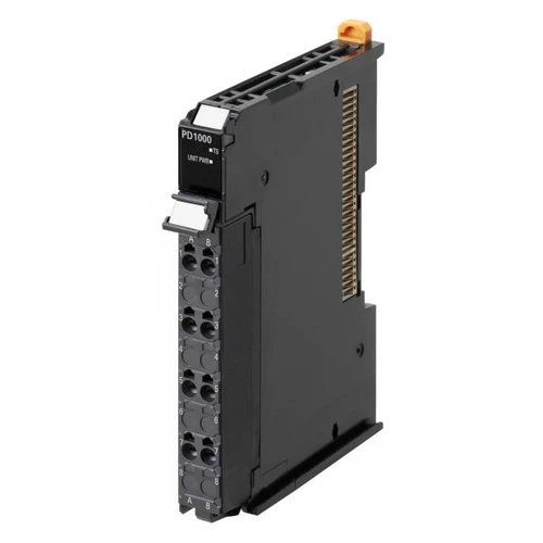
| Unit name | Additional NX Unit Power Supply Unit |
|---|---|
| Model | NX-PD1000 |
| External connection terminals |
Screwless push-in terminal block (8 terminals) |
| Power supply voltage | 24 VDC (20.4 to 28.8 VDC) |
| NX Bus power supply capacity |
10 W max. (Refer to Installation orientation and restrictions for details.) |
| NX Unit power supply efficiency |
70% |
| Unwired terminal current capacity |
4 A max. (Including the current of through-wiring) |
| Dimensions | 12 (W) × 100 (H) 71 × (D) |
| Isolation method | No-isolation |
| Insulation resistance | 20 MΩ min. between isolated circuits (at 100 VDC) |
| Dielectric strength | 510 VAC between isolated circuits for 1 minute at a leakage current of 5 mA max. |
| NX Unit power consumption |
• Connected to a CPU Unit or Communication Control Unit 0.85 W max. • Connected to a Communications Coupler Unit 0.45 W max. |
| I/O current consumption |
No consumption |
| Weight | 65g max. |
| Circuit layout |  |
| Installation orientation and restrictions |
 |
| Terminal connection diagram |
 |
*1. You can use the unwired terminals of the Unit power supply terminals (UV/UG) for through-wiring of the Additional NX
Unit Power Supply Unit or the Unit power supply terminals on the EtherCAT Coupler Unit.
*2. The NC terminal is not connected to the internal circuit.
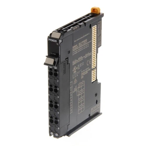
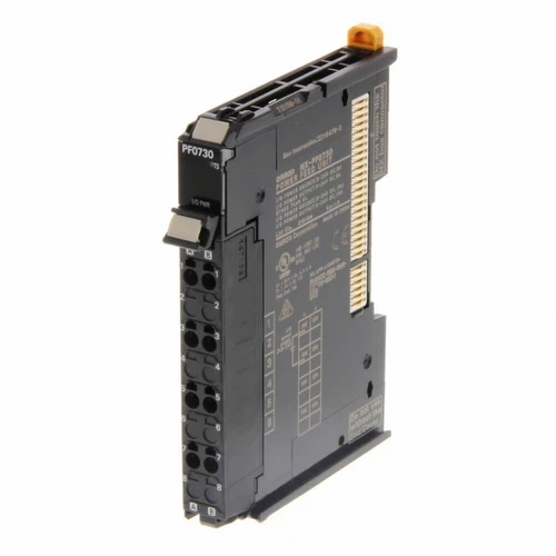
| Unit name | Additional I/O Power Supply Unit | |
|---|---|---|
| Model | NX-PF0630 | NX-PF0730 |
| External connection terminals |
Screwless push-in terminal block (8 terminals) | |
| Power supply voltage | 5 to 24 VDC (4.5 to 28.8 VDC) * | |
| I/O power supply maximum current |
4 A | 10 A |
| Current capacity of I/O power supply terminal |
4 A max. | 10 A max. |
| Dimensions | 12 (W) × 100 (H) 71 × (D) | |
| Isolation method | No-isolation | |
| Insulation resistance | 20 MΩ min. between isolated circuits (at 100 VDC) | |
| Dielectric strength | 510 VAC between isolated circuits for 1 minute at a leakage current of 5 mA max. | |
| NX Unit power consumption |
• Connected to a CPU Unit or Communication Control Unit 0.85 W max. • Connected to a Communications Coupler Unit 0.45 W max. |
|
| I/O current consumption |
10 mA max. | |
| Weight | 65 g max. | |
| Circuit layout |  |
|
| Installation orientation and restrictions |
Installation orientation: • Connected to a CPU Unit or Communication Control Unit: Possible in upright installation. • Connected to a Communications Coupler Unit: Possible in 6 orientations. Restrictions: No restrictions |
|
| Terminal connection diagram |
 |
|
| Overload/low voltage detection |
Not supported | |
| Protective function | Not supported. | |
* Use an output voltage that is appropriate for the I/O circuits of the NX Units and the connected external devices.
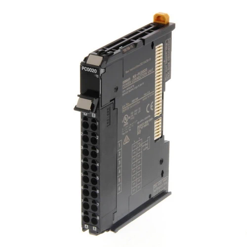
| Unit name | I/O Power Supply Connection Unit |
|---|---|
| Model | NX-PC0010 |
| External connection terminals |
Screwless push-in terminal block (16 terminals) |
| Number of I/O power supply terminals |
IOG: 16 terminals |
| Current capacity of I/O power supply terminal |
4 A/terminal max. |
| Dimensions | 12 (W) × 100 (H) 71 ×(D) |
| Isolation method | No-isolation |
| Insulation resistance | 20 MΩ min. between isolated circuits (at 100 VDC) |
| Dielectric strength | 510 VAC between isolated circuits for 1 minute at a leakage current of 5 mA max. |
| NX Unit power consumption |
• Connected to a CPU Unit or Communication Control Unit 0.85 W max. • Connected to a Communications Coupler Unit 0.45 W max. |
| I/O current consumption |
No consumption |
| Weight | 65 g max. |
| Circuit layout |  |
| Installation orientation and restrictions |
Installation orientation: • Connected to a CPU Unit or Communication Control Unit: Possible in upright installation. • Connected to a Communications Coupler Unit: Possible in 6 orientations. Restrictions: No restrictions |
| Terminal connection diagram |
 |
| Unit name | I/O Power Supply Connection Unit |
|---|---|
| Model | NX-PC0020 |
| External connection terminals |
Screwless push-in terminal block (16 terminals) |
| Number of I/O power supply terminals |
IOV: 16 terminals |
| Current capacity of I/O power supply terminal |
4 A/terminal max. |
| Dimensions | 12 (W) × 100 (H) 71 × (D) |
| Isolation method | No-isolation |
| Isolation resistance | 20 MΩ min. between isolated circuits (at 100 VDC) |
| Dielectric strength | 510 VAC between isolated circuits for 1 minute at a leakage current of 5 mA max. |
| NX Unit power consumption |
• Connected to a CPU Unit or Communication Control Unit 0.85 W max. • Connected to a Communications Coupler Unit 0.45 W max. |
| I/O current consumption |
No consumption |
| Weight | 65 g max. |
| Circuit layout |  |
| Installation orientation and restrictions |
Installation orientation: • Connected to a CPU Unit or Communication Control Unit: Possible in upright installation. • Connected to a Communications Coupler Unit: Possible in 6 orientations. Restrictions: No restrictions |
| Terminal connection diagram |
 |
| Unit name | I/O Power Supply Connection Unit |
|---|---|
| Model | NX-PC0030 |
| External connection terminals |
Screwless push-in terminal block (16 terminals) |
| Number of I/O power supply terminals |
IOV: 8 terminals IOG: 8 terminals |
| Current capacity of I/O power supply terminal |
4 A/terminal max. |
| Dimensions | 12 (W) × 100 (H) 71 × (D) |
| Isolation method | No-isolation |
| Insulation resistance | 20 MΩ min. between isolated circuits (at 100 VDC) |
| Dielectric strength | 510 VAC between isolated circuits for 1 minute at a leakage current of 5 mA max. |
| NX Unit power consumption |
• Connected to a CPU Unit or Communication Control Unit 0.85 W max. • Connected to a Communications Coupler Unit 0.45 W max. |
| I/O current consumption |
No consumption |
| Weight | 65 g max. |
| Circuit layout |  |
| Installation orientation and restrictions |
Installation orientation: • Connected to a CPU Unit or Communication Control Unit: Possible in upright installation. • Connected to a Communications Coupler Unit: Possible in 6 orientations. Restrictions: No restrictions |
| Terminal connection diagram |
 |
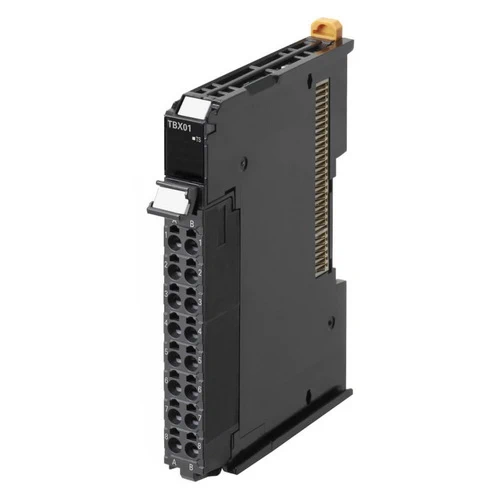
| Unit name | Shield Connection Unit |
|---|---|
| Model | NX-TBX01 |
| External connection terminals |
Screwless push-in terminal block (16 terminals) |
| Number of shield terminals |
14 terminals (The following two terminals are functional ground terminals.) |
| Dimensions | 12 (W) × 100 (H) 71 × (D) |
| Isolation method | Isolation between the SHLD functional ground terminal, and internal circuit: No-isolation |
| Insulation resistance | 20 MΩ min. between isolated circuits (at 100 VDC) |
| Dielectric strength | 510 VAC between isolated circuits for 1 minute at a leakage current of 5 mA max. |
| NX Unit power consumption |
• Connected to a CPU Unit or Communication Control Unit 0.85 W max. • Connected to a Communications Coupler Unit 0.45 W max. |
| I/O current consumption |
No consumption |
| Weight | 65 g max. |
| Circuit layout |  |
| Installation orientation and restrictions |
Installation orientation: • Connected to a CPU Unit or Communication Control Unit: Possible in upright installation. • Connected to a Communications Coupler Unit: Possible in 6 orientations. Restrictions: No restrictions |
| Terminal connection diagram |
 |