| General information |
|
| Article number |
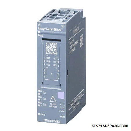
6ES7134-6PA20-0BD0 |
| Product type designation |
AI Energy Meter 480VAC ST |
| Firmware version |
V4.0 |
| ● FW update possible |
Yes |
| usable BaseUnits |
BU type D0 |
| Supported power supply systems |
TT, TN |
| Product function |
|
| ● Voltage measurement |
Yes |
| — without voltage transformer |
Yes |
| — with voltage transformer |
Yes |
| ● Current measurement |
Yes |
| — without current transformer |
No |
| — with current transformer |
Yes |
| — With Rogowski coil |
No |
| — With current-voltage-converter |
No |
| ● Energy measurement |
Yes |
| ● Frequency measurement |
Yes |
| ● Power measurement |
Yes |
| ● Active power measurement |
Yes |
| ● Reactive power measurement |
Yes |
| ● Power factor measurement |
Yes |
| ● Active factor measurement |
No |
| ● Reactive power compensation |
No |
| ● Line analysis |
No |
| ● I&M data |
Yes; I&M0 to I&M3 |
| ● Isochronous mode |
No |
| Engineering with |
|
| ● STEP 7 TIA Portal configurable/integrated from version |
V13 SP1 |
| ● STEP 7 configurable/integrated from version |
V5.5 SP4 and higher |
| ● PROFIBUS from GSD version/GSD revision |
GSD Revision 5 |
| ● PROFINET from GSD version/GSD revision |
V2.3 |
| Operating mode |
|
| ● Cyclic measured value access |
Yes |
| ● Acyclic measured value access |
Yes |
| ● Fixed measured value sets |
Yes |
| ● Freely definable measured value sets |
Yes |
| CiR – Configuration in RUN |
|
| Reparameterization possible in RUN |
Yes |
| Calibration possible in RUN |
Yes |
|
|
| Installation type/mounting |
|
| Mounting position |
any |
| Supply voltage |
|
| Design of the power supply |
Supply via voltage measurement channel L1 |
| Rated value (AC) |
AC 100 – 277 V |
| permissible range, lower limit (AC) |
90 V |
| permissible range, upper limit (AC) |
293 V |
| Line frequency |
|
| ● permissible range, lower limit |
47 Hz |
| ● permissible range, upper limit |
63 Hz |
| Power loss |
|
| Power loss, typ. |
0.6 W |
| Address area |
|
| Address space per module |
|
| ● Inputs |
256 byte |
| ● Outputs |
12 byte |
| Hardware configuration |
|
| Automatic encoding |
Yes |
| ● Mechanical coding element |
Yes |
| ● Type of mechanical coding element |
type C |
| Selection of BaseUnit for connection variants |
|
| ● 2-wire connection |
BU type D0, BU20-P12+A0+0B |
| Time of day |
|
| Operating hours counter |
|
| ● present |
Yes |
| Analog inputs |
|
| Cycle time (all channels), typ. |
50 ms; Time for consistent update of all measured and calculated values (cyclic und acyclic data) |
| Cable length |
|
| ● unshielded, max. |
200 m |
| Analog value generation for the inputs |
|
| Measurement principle |
Sigma Delta |
| Sampling frequency, max. |
1 024 kHz |
| Interrupts/diagnostics/status information |
|
| Alarms |
|
| ● Diagnostic alarm |
Yes |
| ● Limit value alarm |
Yes |
| ● Hardware interrupt |
Yes; Monitoring of up to 16 freely selectable process values (exceeding or undershooting of value) |
| Diagnostics indication LED |
|
| ● Monitoring of the supply voltage (PWR-LED) |
Yes |
| ● Channel status display |
Yes; green LED |
| ● for channel diagnostics |
Yes; red Fn LED |
| ● for module diagnostics |
Yes; green/red DIAG LED |
| Integrated Functions |
|
| Measuring functions |
|
| ● Measuring procedure for voltage measurement |
TRMS |
| ● Measuring procedure for current measurement |
TRMS |
| ● Type of measured value acquisition |
seamless |
| ● Curve shape of voltage |
Sinusoidal or distorted |
| ● Buffering of measured variables |
Yes |
| ● Parameter length |
74 byte |
| ● Bandwidth of measured value acquisition |
2 kHz; Harmonics: 39 / 50 Hz, 32 / 60 Hz |
| Measuring range |
|
| — Frequency measurement, min. |
45 Hz |
| — Frequency measurement, max. |
65 Hz |
| Measuring inputs for voltage |
|
| — Measurable line voltage between phase and neutral conductor |
277 V |
|
|
| — Measurable line voltage between the line conductors |
480 V |
| — Measurable line voltage between phase and neutral conductor, min. |
| — Measurable line voltage between phase and neutral conductor, max. |
90 V |
| — Measurable line voltage between the line conductors, min. |
293 V |
| — Measurable line voltage between the line conductors, max. |
155 V |
| — Internal resistance line conductor and neutral conductor |
508 V |
| — Power consumption per phase |
3.4 MΩ |
| — Impulse voltage resistance 1,2/50µs |
20 mW |
| — Measurement category for voltage |
1 kV |
| measurement in accordance with IEC 61010-2030 |
CAT II; CAT III in case of guaranteed protection level of 1.5 kV |
| Measuring inputs for current |
|
| — measurable relative current (AC), min. |
1 %; Relative to the secondary rated current 5 A |
| — measurable relative current (AC), max. |
100 %; Relative to the secondary rated current 5 A |
| — Continuous current with AC, maximum permissible |
5:00 AM |
| — Apparent power consumption per phase for measuring range 5 A |
0.6 VA |
| — Rated value short-time withstand current restricted to 1 s |
100 A |
| — Input resistance measuring range 0 to 5 A |
25 mΩ; At the terminal |
| — Surge strength |
10 A; for 1 minute |
| — Zero point suppression |
Parameterizable: 2 … 250 mA, default 50 mA |
| Accuracy class according to IEC 61557-12 |
|
| — Measured variable voltage |
0,2 |
| — Measured variable current |
0,2 |
| — Measured variable apparent power |
0.5 |
| — Measured variable active power |
0.5 |
| — Measured variable reactive power |
1 |
| — Measured variable power factor |
0.5 |
| — Measured variable active energy |
0.5 |
| — Measured variable reactive energy |
1 |
| — Measured variable neutral current |
0.5; calculated |
| — Measured variable phase angle |
±1 °; not covered by IEC 61557-12 |
| — Measured variable frequency |
0.05 |
| Potential separation |
|
| Potential separation channels |
|
| ● between the channels |
No |
| ● between the channels and backplane bus |
Yes; 3 700V AC (type test) CAT III |
| Isolation |
|
| Isolation tested with |
2 300V AC for 1 min. (type test) |
| Ambient conditions |
|
| Ambient temperature during operation |
|
| ● horizontal installation, min. |
0 °C |
| ● horizontal installation, max. |
60 °C |
| ● vertical installation, min. |
0 °C |
| ● vertical installation, max. |
50 °C |
| Altitude during operation relating to sea level |
|
| ● Ambient air temperature-barometric pressurealtitude |
On request: Ambient temperatures lower than 0 °C (without condensation) and/or installation altitudes greater than 2 000 m |
| Dimensions |
|
| Width |
20 mm |
| Height |
73 mm |
| Depth |
58 mm |
| Weights |
|
| Weight, approx. |
45 g |
| Other |
|
| Data for selecting a voltage transformer |
|
| ● Secondary side, max. |
296 V |
| Data for selecting a current transformer |
|
| ● Burden power current transformer x/1A, min. ● Burden power current transformer x/5A, min. |
As a function of cable length and cross section, see device manual |
| As a function of cable length and cross section, see device manual |