Analog input modules record process signals such as pressure or temperature and forward them in digitalized 16-bit format to the PLC. They are suitable for measuring voltage, current (2-wire and 4-wire transducers), and resistance, as well as for the connection of resistance thermometers.
Analog output modules convert a 16-bit digital value into a current or a voltage and output this to the process. They are suitable, for example, for controlling proportional valves or small servo drives.
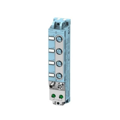
The 30 mm wide I/O modules are especially suitable for use in extremely confined spaces, have settable parameters and diagnostic functions and can thus be adapted flexibly to the respective process requirements.
|
Article number |
6ES7144-5KD00-0BA0 | |
| ET 200AL, AI 4xU/I/RTD, 4xM12 | ||
| General information | ||
| Product type designation | AI 4xU/I/RTD | |
| HW functional status | FS04 | |
| Firmware version | V1.0.x | |
| Product function | ||
| ● I&M data | Yes; I&M0 to I&M3 | |
| Engineering with | ||
| ● STEP 7 TIA Portal configurable/integrated from version | STEP 7 V13 SP1 or higher | |
| ● STEP 7 configurable/integrated from version | From V5.5 SP4 Hotfix 3 | |
| ● PROFIBUS from GSD version/GSD revision | GSD as of Revision 5 | |
| ● PROFINET from GSD version/GSD revision | GSDML V2.3.1 | |
| Supply voltage | ||
| power supply according to NEC Class 2 required | No | |
| Load voltage 1L+ | ||
| ● Rated value (DC) | 24 V | |
| ● permissible range, lower limit (DC) | 20.4 V | |
| ● permissible range, upper limit (DC) | 28.8 V | |
| ● Reverse polarity protection | Yes; against destruction | |
| Input current | ||
| Current consumption (rated value) | 35 mA; without load | |
| from load voltage 1L+ (unswitched voltage) | 4 A; Maximum value | |
| from load voltage 2L+, max. | 4 A; Maximum value | |
| Encoder supply | ||
| Number of outputs | 4 | |
| 24 V encoder supply | ||
| ● Short-circuit protection | Yes; per channel, electronic | |
| ● Output current, max. | 0.5 A; Per channel, total current of all channels max. 1 A | |
| Power loss | ||
| Power loss, typ. | 1.5 W | |
| Analog inputs | ||
| Number of analog inputs | 4 | |
| ● For current measurement | 4 | |
| ● For voltage measurement | 4 | |
| ● For resistance/resistance thermometer measurement | 4 | |
| ● For thermocouple measurement | ||
| permissible input voltage for voltage input (destruction limit), max. | 30 V | |
| permissible input current for current input (destruction limit), max. | 50 mA | |
| Constant measurement current for resistance-type transmitter, typ. | ||
| Cycle time (all channels), min. | 8 ms | |
| Technical unit for temperature measurement adjustable | Yes; Degrees Celsius / degrees Fahrenheit / Kelvin | |
| Input ranges (rated values), voltages | ||
| ● 0 to +10 V | Yes | |
| — Input resistance (0 to 10 V) | 10 MΩ | |
| ● 1 V to 5 V | Yes | |
| — Input resistance (1 V to 5 V) | 10 MΩ | |
| ● -80 mV to +80 mV | ||
| — Input resistance (-80 mV to +80 mV) | ||
| Input ranges (rated values), currents | ||
| ● 0 to 20 mA | Yes | |
| — Input resistance (0 to 20 mA) | 50 Ω | |
| ● 4 mA to 20 mA | Yes | |
| — Input resistance (4 mA to 20 mA) | 50 Ω | |
| Input ranges (rated values), thermocouples | ||
| ● Type B | ||
| — Input resistance (Type B) | ||
| ● Type C | ||
| — Input resistance (Type C) | ||
| ● Type E | ||
| — Input resistance (Type E) | ||
| ● Type J | ||
| — Input resistance (type J) | ||
| ● Type K | ||
| — Input resistance (Type K) | ||
| ● Type L | ||
| — Input resistance (Type L) | ||
| ● Type N | ||
| — Input resistance (Type N) | ||
| ● Type R | ||
| — Input resistance (Type R) | ||
| ● Type S | ||
| — Input resistance (Type S) | ||
| ● Type T | ||
| — Input resistance (Type T) | ||
| ● Type U | ||
| — Input resistance (Type U) | ||
| Input ranges (rated values), resistance thermometer | ||
| ● Ni 100 | Yes; Standard/climate | |
| — Input resistance (Ni 100) | 10 MΩ | |
| ● Ni 1000 | ||
| — Input resistance (Ni 1000) | ||
| ● Pt 100 | Yes; Standard/climate | |
| — Input resistance (Pt 100) | 10 MΩ | |
| ● Pt 1000 | ||
| — Input resistance (Pt 1000) | ||
| Input ranges (rated values), resistors | ||
| ● 0 to 150 ohms | Yes | |
| — Input resistance (0 to 150 ohms) | 10 MΩ | |
| ● 0 to 300 ohms | Yes | |
| — Input resistance (0 to 300 ohms) | 10 MΩ | |
| Thermocouple (TC) | ||
| Temperature compensation | ||
| — parameterizable | ||
| — internal temperature compensation | ||
| — external temperature compensation with compensations socket | ||
| — dynamic reference temperature value | ||
| — fixed reference temperature | ||
| Cable length | ||
| ● shielded, max. | 30 m | |
| Analog value generation for the inputs | ||
| Measurement principle | integrating | |
| Integration and conversion time/resolution per channel | ||
| ● Resolution with overrange (bit including sign), max. | 16 bit | |
| ● Integration time, parameterizable | Yes; channel by channel | |
| ● Integration time (ms) | 0,3 / 16,7 / 20 / 60 | |
| ● Basic conversion time, including integration time (ms) | ||
| — additional conversion time for wire-break monitoring | ||
| — additional conversion time for resistance measurement | ||
| ● Interference voltage suppression for interference frequency f1 in Hz | 3 600 / 60 / 50 / 16.7 | |
| ● Conversion time (per channel) | 2 / 18 / 21 / 61 ms | |
| Smoothing of measured values | ||
| ● parameterizable | Yes | |
| ● Step: None | Yes; 1x cycle time | |
| ● Step: low | Yes; 4x cycle time | |
| ● Step: Medium | Yes; 16x cycle time | |
| ● Step: High | Yes; 32x cycle time | |
| Encoder | ||
| Connection of signal encoders | ||
| ● for voltage measurement | Yes | |
| ● for current measurement as 2-wire transducer | Yes | |
| ● for current measurement as 4-wire transducer | Yes | |
| ● for resistance measurement with two-wire connection | Yes | |
| ● for resistance measurement with three-wire connection | Yes | |
| ● for resistance measurement with four-wire connection | ||
| Errors/accuracies | ||
| Linearity error (relative to input range), (+/-) | 0.025 % | |
| Temperature error (relative to input range), (+/-) | 0.01 %/K | |
| Crosstalk between the inputs, max. | -70 dB | |
| Repeat accuracy in steady state at 25 °C (relative to input range), (+/-) | 0.01 % | |
| Temperature error of internal compensation | ||
| Operational error limit in overall temperature range | ||
| ● Voltage, relative to input range, (+/-) | 0.35 % | |
| ● Current, relative to input range, (+/-) | 0.45 % | |
| ● Resistance, relative to input range, (+/-) | 0.25 % | |
| ● Resistance thermometer, relative to input range, (+/-) | 0.25 % | |
| ● Thermocouple, relative to input range, (+/-) | ||
| Basic error limit (operational limit at 25 °C) | ||
| ● Voltage, relative to input range, (+/-) | 0.25 % | |
| ● Current, relative to input range, (+/-) | 0.25 % | |
| ● Resistance, relative to input range, (+/-) | 0.15 % | |
| ● Resistance thermometer, relative to input range, (+/-) | 0.15 % | |
| ● Thermocouple, relative to input range, (+/-) | ||
| Interference voltage suppression for f = n x (f1 +/- 0.5 %), f1 = interference frequency | ||
| ● Series mode interference (peak value of interference < rated value of input range), min. | 40 dB | |
| Interrupts/diagnostics/status information | ||
| Alarms | ||
| ● Diagnostic alarm | Yes; Parameterizable | |
| ● Limit value alarm | Yes; Parameterizable | |
| Diagnoses | ||
| ● Wire-break | Yes; at 4 mA to 20 mA and 1 V to 5 V | |
| ● Short-circuit | Yes; Encoder supply to M, channel by channel | |
| ● Overflow/underflow | Yes | |
| Diagnostics indication LED | ||
| ● Channel status display | Yes; green LED | |
| ● for module diagnostics | Yes; green/red LED | |
| Potential separation | ||
| between the load voltages | Yes | |
| Potential separation channels | ||
| ● between the channels | No | |
| ● between the channels and backplane bus | Yes | |
| ● between the channels and the power supply of the electronics | No | |
| Isolation | ||
| Isolation tested with | 707 V DC (type test) | |
| Degree and class of protection | ||
| IP degree of protection | IP65/67 | |
| Standards, approvals, certificates | ||
| Suitable for safety-related tripping of standard modules | Yes; From FS02 | |
| Suitable for applications according to AMS 2750 | ||
| Suitable for applications according to CQI-9 | ||
| Highest safety class achievable for safety-related tripping of standard modules | ||
| ● Performance level according to ISO 13849-1 | PL d | |
| ● Category according to ISO 13849-1 | Cat. 3 | |
| ● SIL acc. to IEC 62061 | SIL 2 | |
| ● remark on safety-oriented shutdown | https://support.industry.siemens.com/cs/de/en/view/39198632 | |
| Ambient conditions | ||
| Ambient temperature during operation | ||
| ● min. | -30 °C | |
| ● max. | 55 °C | |
| connection method / header | ||
| Design of electrical connection for the inputs and outputs | M12, 5-pole | |
| Design of electrical connection for supply voltage | M8, 4-pole | |
| ET-Connection | ||
| ● ET-Connection | M8, 4-pin, shielded | |
| Dimensions | ||
| Width | 30 mm | |
| Height | 159 mm | |
| Depth | 40 mm | |
| Weights | ||
| Weight, approx. | 168 g | |