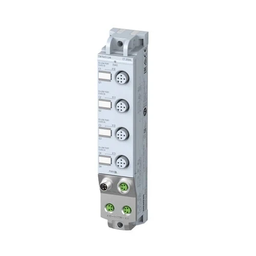
The CM IO-Link communication module enables data exchange with up to 4 IO-Link devices.
IO-Link devices (e.g. sensors) with a Class A port are connected using a 3-wire cable. IO-Link devices that require additional supply voltage and have a Class B port (e.g. actuators) are connected using a 5-wire cable.
Thanks to the compatibility of IO-Link with standard sensors, commercially available sensors in accordance with IEC 61131 Type 1 can also be operated on the IO-Link master.
The 30 mm wide I/O modules are especially suitable for use in extremely confined spaces, have settable parameters and diagnostic functions and can thus be adapted flexibly to the respective process requirements.
| Article number | 6ES7147-5JD00-0BA0 |
| ET 200AL, cm 4x IO-Link, 4xM12 | |
| General information | |
| Product type designation | CM 4x IO-Link |
| HW functional status | FS05 |
| Firmware version | V1.2.x |
| Product function | |
| ● I&M data | Yes; I&M0 to I&M3 |
| Engineering with | |
| ● STEP 7 TIA Portal configurable/integrated from version | STEP 7 V13 SP1 or higher |
| ● STEP 7 configurable/integrated from version | From V5.5 SP4 Hotfix 3 |
| ● PROFIBUS from GSD version/GSD revision | GSD as of Revision 5 |
| ● PROFINET from GSD version/GSD revision | GSDML V2.3.1 |
| Supply voltage | |
| power supply according to NEC Class 2 required | No |
| Load voltage 1L+ | |
| ● Rated value (DC) | 24 V |
| ● permissible range, lower limit (DC) | 20.4 V |
| ● permissible range, upper limit (DC) | 28.8 V |
| ● Reverse polarity protection | Yes |
| Load voltage 2L+ | |
| ● Rated value (DC) | 24 V |
| ● permissible range, lower limit (DC) | 20.4 V |
| ● permissible range, upper limit (DC) | 28.8 V |
| ● Reverse polarity protection | Yes; against destruction; load increasing |
| Input current | |
| Current consumption (rated value) | 40 mA; without load |
| from load voltage 1L+ (unswitched voltage) | 4 A; Maximum value |
| from load voltage 2L+, max. | 4 A; Maximum value |
| Encoder supply | |
| Number of outputs | 4 |
| 24 V encoder supply | |
| ● Short-circuit protection | Yes; per module, electronic |
| ● Output current, max. | 1.4 A; Total current of all ports |
| Power loss | |
| Power loss, typ. | 2.6 W |
| IO-Link | |
| Number of ports | 4 |
| ● of which simultaneously controllable | 4 |
| IO-Link protocol 1.0 | Yes |
| IO-Link protocol 1.1 | Yes |
| Transmission rate | 4.8 kBaud (COM1); 38.4 kBaud (COM2), 230 kBaud (COM3) |
| Size of process data, input per port | 32 byte |
| Size of process data, input per module | 132 byte |
| Size of process data, output per port | 32 byte |
| Size of process data, output per module | 128 byte |
| Memory size for device parameter | 2 kbyte; for each port |
| Master backup | Possible with function block IO_LINK_MASTER |
| Configuration without S7-PCT | Possible; autostart/manual function |
| Cable length unshielded, max. | 20 m |
| Operating modes | |
| ● IO-Link | Yes |
| ● DI | Yes |
| ● DQ | Yes; max. 100 mA |
| Connection of IO-Link devices | |
| ● Port type A | Yes; via 3-core cable |
| ● Port type B | Yes; Additional device supply: 1.6 A total current of all ports |
| Interrupts/diagnostics/status information | |
| Alarms | |
| ● Diagnostic alarm | Yes; Parameterizable |
| Diagnoses | |
| ● Monitoring the supply voltage | Yes |
| ● Wire-break | Yes |
| ● Short-circuit | Yes |
| Diagnostics indication LED | |
| ● Channel status display | Yes; green LED |
| ● for module diagnostics | Yes; green/red LED |
| ● For load voltage monitoring | Yes; green LED |
| Potential separation | |
| between the load voltages | Yes |
| Potential separation channels | |
| ● between the channels | No |
| ● between the channels and backplane bus | Yes |
| ● between the channels and the power supply of the electronics | No |
| Isolation | |
| Isolation tested with | 707 V DC (type test) |
| Degree and class of protection | |
| IP degree of protection | IP65/67 |
| Standards, approvals, certificates | |
| Suitable for safety-related tripping of standard modules | Yes; From FS01 |
| Highest safety class achievable for safety-related tripping of standard modules | |
| ● Performance level according to ISO 13849-1 | PL d |
| ● Category according to ISO 13849-1 | Cat. 3 |
| ● SILCL according to IEC 62061 | SILCL 2 |
| Ambient conditions | |
| Ambient temperature during operation | |
| ● min. | -30 °C |
| ● max. | 55 °C |
| connection method / header | |
| Design of electrical connection for the inputs and outputs | M12, 5-pole |
| Design of electrical connection for supply voltage | M8, 4-pole |
| ET-Connection | |
| ● ET-Connection | M8, 4-pin, shielded |
| Dimensions | |
| Width | 30 mm |
| Height | 159 mm |
| Depth | 40 mm |
| Weights | |
| Weight, approx. | 145 g |