Analog inputs record process signals such as pressure or temperature and forward them in digitalized format (16-bit format) to the PLC. They are suitable for measuring voltage, current (2-wire and 4-wire transmitters), resistance, resistance thermometers and the connection of thermocouples.
Analog outputs convert a 16-bit digital value into a current or a voltage and output this to the process. They are suitable, for example, for controlling proportional valves or small servo drives.
All I/O devices have configurable parameters and diagnostic functions and can thus be freely adapted to the respective process requirements.
| Article number | 6ES7144-6KD00-0AB0 |
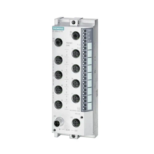
| ET200eco PN, 8AI; 4 U/I; 4 RTD/TC 8xM12 | |
| General information | |
| HW functional status | |
| Firmware version | |
| ● FW update possible | |
| Vendor identification (VendorID) | 002AH |
| Device identifier (DeviceID) | 0306H |
| Manufacturer ID according to ODVA (VendorID) | |
| Device ID according to ODVA (Product code) | |
| Product function | |
| ● I&M data | |
| ● Isochronous mode | |
| ● Prioritized startup | |
| ● Measuring range scalable | |
| Engineering with | |
| ● STEP 7 TIA Portal configurable/integrated from version | |
| ● PROFINET from GSD version/GSD revision | |
| ● Multi Fieldbus Configuration Tool (MFCT) | |
| Operating mode | |
| ● MSI | |
| CiR – Configuration in RUN | |
| Calibration possible in RUN | |
| Supply voltage | |
| Rated value (DC) | 24 V |
| Reverse polarity protection | Yes |
| power supply according to NEC Class 2 required | Yes |
| Load voltage 1L+ | |
| ● Rated value (DC) | |
| ● permissible range, lower limit (DC) | |
| ● permissible range, upper limit (DC) | |
| ● Reverse polarity protection | |
| Input current | |
| Current consumption (rated value) | |
| Current consumption, typ. | 110 mA |
| from load voltage 1L+ (unswitched voltage) | |
| from load voltage 2L+, max. | |
| Encoder supply | |
| Number of outputs | 4 |
| 24 V encoder supply | |
| ● Short-circuit protection | Yes; Electronic at 1.4 A |
| ● Output current, max. | 1 A |
| Power loss | |
| Power loss, typ. | 2.8 W |
| Address area | |
| Address space per module | |
| ● Inputs | |
| Hardware configuration | |
| Submodules | |
| ● Number of configurable submodules, max. | |
| Analog inputs | |
| Number of analog inputs | 8 |
| ● For voltage/current measurement | 4 |
| ● For voltage measurement | |
| ● For resistance/resistance thermometer measurement | 4 |
| ● For thermocouple measurement | |
| permissible input voltage for voltage input (destruction limit), max. | 28.8 V permanent, 35 V for max. 500 ms |
| Constant measurement current for resistance-type transmitter, typ. | |
| Cycle time (all channels), min. | |
| Technical unit for temperature measurement adjustable | |
| Input ranges (rated values), voltages | |
| ● 0 to +10 V | Yes |
| ● 1 V to 5 V | Yes |
| ● -10 V to +10 V | Yes |
| ● -80 mV to +80 mV | Yes |
| — Input resistance (-80 mV to +80 mV) | |
| Input ranges (rated values), currents | |
| ● 0 to 20 mA | Yes |
| ● -20 mA to +20 mA | Yes |
| ● 4 mA to 20 mA | Yes |
| Input ranges (rated values), thermocouples | |
| ● Type B | |
| — Input resistance (Type B) | |
| ● Type C | |
| — Input resistance (Type C) | |
| ● Type E | Yes |
| — Input resistance (Type E) | |
| ● Type J | Yes |
| — Input resistance (type J) | |
| ● Type K | Yes |
| — Input resistance (Type K) | |
| ● Type L | |
| — Input resistance (Type L) | |
| ● Type N | Yes |
| — Input resistance (Type N) | |
| ● Type R | |
| — Input resistance (Type R) | |
| ● Type S | |
| — Input resistance (Type S) | |
| ● Type T | |
| — Input resistance (Type T) | |
| ● Type U | |
| — Input resistance (Type U) | |
| Input ranges (rated values), resistance thermometer | |
| ● Ni 100 | Yes |
| — Input resistance (Ni 100) | |
| ● Ni 1000 | Yes |
| — Input resistance (Ni 1000) | |
| ● Ni 120 | Yes |
| — Input resistance (Ni 120) | |
| ● Ni 200 | Yes |
| — Input resistance (Ni 200) | |
| ● Ni 500 | Yes |
| — Input resistance (Ni 500) | |
| ● Pt 100 | Yes |
| — Input resistance (Pt 100) | |
| ● Pt 1000 | Yes |
| — Input resistance (Pt 1000) | |
| ● Pt 200 | Yes |
| — Input resistance (Pt 200) | |
| ● Pt 500 | Yes |
| — Input resistance (Pt 500) | |
| Input ranges (rated values), resistors | |
| ● 0 to 150 ohms | Yes |
| — Input resistance (0 to 150 ohms) | |
| ● 0 to 300 ohms | Yes |
| — Input resistance (0 to 300 ohms) | |
| ● 0 to 600 ohms | Yes |
| — Input resistance (0 to 600 ohms) | |
| ● 0 to 3000 ohms | Yes |
| — Input resistance (0 to 3000 ohms) | |
| ● 0 to 6000 ohms | |
| — Input resistance (0 to 6000 ohms) | |
| Thermocouple (TC) | |
| Temperature compensation | |
| — parameterizable | Yes |
| — internal temperature compensation | Yes |
| — external temperature compensation with Pt100 | |
| — external temperature compensation with compensations socket | Yes |
| — dynamic reference temperature value | |
| — for definable comparison point temperature | |
| — fixed reference temperature | |
| Cable length | |
| ● shielded, max. | 30 m |
| Analog value generation for the inputs | |
| Analog value display | SIMATIC S7 format |
| Measurement principle | integrating |
| Integration and conversion time/resolution per channel | |
| ● Resolution with overrange (bit including sign), max. | 16 bit |
| ● Integration time, parameterizable | Yes |
| ● Integration time (ms) | 2/16.67/20/100 ms |
| ● Basic conversion time, including integration time (ms) | |
| — additional conversion time for wire-break monitoring | |
| ● Interference voltage suppression for interference frequency f1 in Hz | 500 / 60 / 50 / 10 Hz |
| ● Conversion time (per channel) | 4 / 19 / 22 / 102 ms |
| Smoothing of measured values | |
| ● parameterizable | Yes |
| ● Step: None | Yes; 1x cycle time |
| ● Step: low | Yes; 4x cycle time |
| ● Step: Medium | Yes; 16x cycle time |
| ● Step: High | Yes; 64x cycle time |
| Encoder | |
| Number of connectable encoders, max. | 8 |
| Connection of signal encoders | |
| ● for voltage measurement | Yes |
| ● for current measurement as 2-wire transducer | Yes |
| ● for current measurement as 4-wire transducer | Yes |
| ● for resistance measurement with two-wire connection | Yes |
| ● for resistance measurement with three-wire connection | Yes |
| ● for resistance measurement with four-wire connection | Yes |
| Errors/accuracies | |
| Linearity error (relative to input range), (+/-) | 0.01 % |
| Temperature error (relative to input range), (+/-) | U: 0.0035%/°C; I:0.006%/°C; RTD: 0.0005%/°C; TC: 0.0035%/°C |
| Crosstalk between the inputs, min. | 85 dB |
| Crosstalk between the inputs, max. | |
| Repeat accuracy in steady state at 25 °C (relative to input range), (+/-) | 0.008 % |
| Temperature error of internal compensation | |
| Operational error limit in overall temperature range | |
| ● Voltage, relative to input range, (+/-) | |
| ● Resistance, relative to input range, (+/-) | |
| ● Resistance thermometer, relative to input range, (+/-) | |
| ● Thermocouple, relative to input range, (+/-) | |
| Basic error limit (operational limit at 25 °C) | |
| ● Voltage, relative to input range, (+/-) | |
| ● Resistance, relative to input range, (+/-) | |
| ● Resistance thermometer, relative to input range, (+/-) | |
| ● Thermocouple, relative to input range, (+/-) | |
| Interference voltage suppression for f = n x (f1 +/- 1 %), f1 = interference frequency | |
| ● Series mode interference (peak value of interference < rated value of input range), min. | 46 dB |
| ● Common mode interference, min. | 70 dB |
| Interference voltage suppression for f = n x (f1 +/- 0.5 %), f1 = interference frequency | |
| ● Series mode interference (peak value of interference < rated value of input range), min. | |
| Interfaces | |
| Transmission procedure | 100BASE-TX |
| Number of PROFINET interfaces | 1 |
| 1. Interface | |
| Interface type | |
| Interface types | |
| ● M12 port | Yes |
| ● Number of ports | |
| ● integrated switch | Yes |
| Protocols | |
| ● PROFINET IO Device | |
| ● Open IE communication | |
| Interface types | |
| M12 port | |
| ● Autonegotiation | Yes |
| ● Autocrossing | Yes |
| ● Transmission rate, max. | 100 Mbit/s |
| Protocols | |
| Supports protocol for PROFINET IO | Yes |
| PROFINET CBA | No |
| PROFIsafe | No |
| EtherNet/IP | |
| Modbus TCP | |
| PROFINET IO Device | |
| Services | |
| — IRT | |
| — IRT with the option “high flexibility” | Yes |
| — Prioritized startup | Yes |
| — Shared device | |
| — Number of IO Controllers with shared device, max. | |
| Redundancy mode | |
| ● PROFINET system redundancy (S2) | |
| — on S7-1500R/H | |
| — on S7-400H | |
| ● PROFINET system redundancy (R1) | |
| ● H-Sync forwarding | |
| Media redundancy | |
| — MRP | Yes |
| EtherNet/IP | |
| Services | |
| — CIP Implicit Messaging | |
| — CIP Explicit Messaging | |
| — CIP Safety | |
| — Shared device | |
| — Number of scanners with shared device, max. | |
| Updating times | |
| — Requested Packet Interval (RPI) | |
| Redundancy mode | |
| — DLR (Device Level Ring) | |
| Address area | |
| — Address space per module, max. | |
| — LargeForwardOpen (Class3) | |
| Modbus TCP | |
| Services | |
| — read coils (code=1) | |
| — read discrete inputs (code=2) | |
| — Read Holding Registers (Code=3) | |
| — write single coil (code=5) | |
| — write multiple coils (code=15) | |
| — Write Multiple Registers (Code=16) | |
| — Parameter change by master | |
| — Modbus TCP Security Protocol | |
| Address space per station | |
| — Address space per station, max. | |
| — Access-consistent address space | |
| Updating time | |
| — I/O request interval | |
| Connections | |
| — Number of connections per slave | |
| Open IE communication | |
| ● TCP/IP | No |
| ● SNMP | Yes |
| ● DCP | Yes |
| ● LLDP | Yes |
| ● ping | Yes |
| ● ARP | Yes |
| Interrupts/diagnostics/status information | |
| Diagnostics function | Yes |
| Alarms | |
| ● Diagnostic alarm | Yes |
| ● Maintenance interrupt | |
| ● Limit value alarm | |
| Diagnoses | |
| ● Diagnostic information readable | Yes |
| ● Monitoring the supply voltage | Yes; green “ON” LED |
| — parameterizable | |
| ● Wire-break | |
| ● Short-circuit encoder supply | Yes; per module |
| ● Group error | Yes; Red/yellow “SF/MT” LED |
| ● Overflow/underflow | Yes |
| Diagnostics indication LED | |
| ● RUN LED | |
| ● ERROR LED | |
| ● MAINT LED | |
| ● NS LED | |
| ● MS LED | |
| ● IO LED | |
| ● Channel status display | |
| ● for channel diagnostics | |
| ● Connection display LINK TX/RX | |
| Potential separation | |
| between the load voltages | Yes |
| between load voltage and all other switching components | No |
| between Ethernet and electronics | Yes |
| Potential separation channels | |
| ● between the channels | No |
| ● between the channels and the power supply of the electronics | |
| Permissible potential difference | |
| Between the inputs and MANA (UCM) | 10 Vpp AC |
| Isolation | |
| tested with | |
| ● 24 V DC circuits | 707 V DC (type test) |
| ● Test voltage for interface, rms value [Vrms] | 1 500 V; According to IEEE 802.3 |
| Degree and class of protection | |
| IP degree of protection | IP65/67 |
| Standards, approvals, certificates | |
| Suitable for applications according to AMS 2750 | Yes; Declaration of Conformity, see online support entry 109757262 |
| Suitable for applications according to CQI-9 | Yes; Based on AMS 2750 E |
| Ambient conditions | |
| Ambient temperature during operation | |
| ● min. | |
| ● max. | |
| Altitude during operation relating to sea level | |
| ● Ambient air temperature-barometric pressure-altitude | |
| connection method / header | |
| Design of electrical connection | 4/5-pin M12 circular connectors |
| Design of electrical connection for the inputs and outputs | |
| Design of electrical connection for supply voltage | |
| Dimensions | |
| Width | 60 mm |
| Height | 175 mm |
| Depth | 49 mm |
| Weights | |
| Weight, approx. | 930 g |