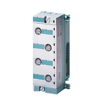
Analog expansion modules permit the connection of sensors/actuators to ET 200pro via integrated inputs and outputs.
| Article number | 6ES7144-4FF01-0AB0 | 6ES7144-4GF01-0AB0 | 6ES7144-4JF00-0AB0 | 6ES7144-4PF00-0AB0 |
| ET 200pro, EM 4AI-U HF | ET 200pro, EM 4AI-I HF | ET 200pro, EM 4 AI-RTD HF | ET 200pro, EM 4 AI-TC HF | |
| Supply voltage | ||||
| Rated value (DC) | 24 V | 24 V | 24 V | 24 V |
| Reverse polarity protection | Yes; against destruction | Yes; against destruction | Yes; against destruction | Yes; against destruction |
| Input current | ||||
| from supply voltage 1L+, max. | 40 mA; Typical | 40 mA; Typical | 27 mA; Typical | 34 mA; Typical |
| from backplane bus 3.3 V DC, max. | 12 mA; Typical | 12 mA; Typical | 10 mA; Typical | 20 mA; Typical |
| Encoder supply | ||||
| Number of outputs | 4 | 4 | ||
| Short-circuit protection | Yes; per module, electronic to frame | Yes; per module, electronic to frame | ||
| Output current | ||||
| ● up to 55 °C, max. | 1 A | 1 A | ||
| Power loss | ||||
| Power loss, typ. | 1.1 W | 1.1 W | 0.7 W | 0.7 W |
| Address area | ||||
| Address space per module | ||||
| ● Address space per module, max. | 8 byte | 8 byte | 8 byte | 8 byte |
| Analog inputs | ||||
| Number of analog inputs | 4 | 4 | 4 | 4 |
| permissible input voltage for voltage input (destruction limit), max. | 35 V | 20 V | ||
| permissible input current for current input (destruction limit), max. | 40 mA | |||
| Constant measurement current for resistance-type transmitter, typ. | 1.25 mA; 1.25 / 0.5 mA depending on measuring range | |||
| Cycle time (all channels) max. | 5 ms | 10 ms | 83 ms; 83 ms at 50 Hz; 69 ms at 60 Hz | Number of active channels per module x basic conversion time |
| Technical unit for temperature measurement adjustable | Yes; Degrees Celsius/degrees Fahrenheit | Yes; °C/°F/K | ||
| Input ranges (rated values), voltages | ||||
| ● 0 to +10 V | Yes | |||
| ● 1 V to 5 V | Yes | |||
| ● -10 V to +10 V | Yes | |||
| ● -5 V to +5 V | Yes | |||
| ● -80 mV to +80 mV | Yes | |||
| — Input resistance (-80 mV to +80 mV) | 10 MΩ | |||
| Input ranges (rated values), currents | ||||
| ● 0 to 20 mA | Yes | |||
| — Input resistance (0 to 20 mA) | 50 Ω | |||
| ● -20 mA to +20 mA | Yes | |||
| — Input resistance (-20 mA to +20 mA) | 50 Ω | |||
| ● 4 mA to 20 mA | Yes | |||
| — Input resistance (4 mA to 20 mA) | 50 Ω | |||
| Input ranges (rated values), thermocouples | ||||
| ● Type B | Yes | |||
| — Input resistance (Type B) | 10 MΩ | |||
| ● Type E | Yes | |||
| — Input resistance (Type E) | 10 MΩ | |||
| ● Type J | Yes | |||
| — Input resistance (type J) | 10 MΩ | |||
| ● Type K | Yes | |||
| — Input resistance (Type K) | 10 MΩ | |||
| ● Type L | Yes | |||
| — Input resistance (Type L) | 10 MΩ | |||
| ● Type N | Yes | |||
| — Input resistance (Type N) | 10 MΩ | |||
| ● Type R | Yes | |||
| — Input resistance (Type R) | 10 MΩ | |||
| ● Type S | Yes | |||
| — Input resistance (Type S) | 10 MΩ | |||
| ● Type T | Yes | |||
| — Input resistance (Type T) | 10 MΩ | |||
| Input ranges (rated values), resistance thermometer | ||||
| ● Cu 10 | No | |||
| ● Ni 100 | Yes | |||
| — Input resistance (Ni 100) | 10 000 kΩ | |||
| ● Ni 1000 | Yes | |||
| — Input resistance (Ni 1000) | 10 000 kΩ | |||
| ● Ni 120 | Yes | |||
| — Input resistance (Ni 120) | 10 000 kΩ | |||
| ● Ni 200 | Yes | |||
| — Input resistance (Ni 200) | 10 000 kΩ | |||
| ● Ni 500 | Yes | |||
| — Input resistance (Ni 500) | 10 000 kΩ | |||
| ● Pt 100 | Yes | |||
| — Input resistance (Pt 100) | 10 000 kΩ | |||
| ● Pt 1000 | Yes | |||
| — Input resistance (Pt 1000) | 10 000 kΩ | |||
| ● Pt 200 | Yes | |||
| — Input resistance (Pt 200) | 10 000 kΩ | |||
| ● Pt 500 | Yes | |||
| — Input resistance (Pt 500) | 10 000 kΩ | |||
| Input ranges (rated values), resistors | ||||
| ● 0 to 150 ohms | Yes | |||
| — Input resistance (0 to 150 ohms) | 10 000 kΩ | |||
| ● 0 to 300 ohms | Yes | |||
| — Input resistance (0 to 300 ohms) | 10 000 kΩ | |||
| ● 0 to 600 ohms | Yes | |||
| — Input resistance (0 to 600 ohms) | 10 000 kΩ | |||
| ● 0 to 3000 ohms | Yes | |||
| — Input resistance (0 to 3000 ohms) | 10 000 kΩ | |||
| Thermocouple (TC) | ||||
| Temperature compensation | ||||
| — internal temperature compensation | Yes | |||
| — external temperature compensation with compensations socket | Yes | |||
| Characteristic linearization | ||||
| ● parameterizable | Yes | |||
| — for resistance thermometer | Ptxxx, Nixxx | |||
| Cable length | ||||
| ● shielded, max. | 30 m | 30 m | 30 m | 30 m |
| Analog value generation for the inputs | ||||
| Measurement principle | integrating | integrating | integrating | integrating |
| Integration and conversion time/resolution per channel | ||||
| ● Resolution with overrange (bit including sign), max. | 15 bit; 15 bit + sign at ±10 V, at ±5 V; 15 bit at 0 V to 10 V, at 1 V to 5 V | 15 bit; 15 bit + sign at ±10 V, at ±5 V; 15 bit at 0 V to 10 V, at 1 V to 5 V | 15 bit; at 150, 300, 600 und 3 000 ohms; otherwise 15 bits + sign | 15 bit; + sign |
| ● Integration time (ms) | 0,3 / 16,7 / 20 / 60 | 0,3 / 16,7 / 20 / 60 | 20 / 16,667 | 2,5 / 16,67 / 20 / 100 ms |
| ● Interference voltage suppression for interference frequency f1 in Hz | 16,67 / 50 / 60 / 3 600 | 16,67 / 50 / 60 / 3 600 | 50 / 60 Hz | 10 / 50 / 60 / 400 Hz |
| ● Conversion time (per channel) | 1.1 ms | 1.1 ms | 20.625 ms; 20.625 ms at 50 Hz; 17.25 ms at 60 Hz | 4.7/19/22/102 ms |
| Smoothing of measured values | ||||
| ● parameterizable | Yes | Yes | Yes | Yes |
| ● Step: None | Yes; 1x cycle time | Yes; 1x cycle time | Yes; 1x cycle time | Yes; 1x cycle time |
| ● Step: low | Yes; 4x cycle time | Yes; 4x cycle time | Yes; 4x cycle time | Yes; 4x cycle time |
| ● Step: Medium | Yes; 16x cycle time | Yes; 16x cycle time | Yes; 16x cycle time | Yes; 16x cycle time |
| ● Step: High | Yes; 64x cycle time | Yes; 64x cycle time | Yes; 64x cycle time | Yes; 64x cycle time |
| Encoder | ||||
| Connection of signal encoders | ||||
| ● for voltage measurement | Yes | Yes | ||
| ● for current measurement as 2-wire transducer | Yes | |||
| ● for current measurement as 4-wire transducer | Yes | |||
| ● for resistance measurement with two-wire connection | Yes; Line resistances are also measured | |||
| ● for resistance measurement with three-wire connection | Yes | |||
| ● for resistance measurement with four-wire connection | Yes | |||
| Errors/accuracies | ||||
| Linearity error (relative to input range), (+/-) | 0.0075 % | 0.0075 % | 0.05 % | 0.01 % |
| Temperature error (relative to input range), (+/-) | 0.00075 %/K | 0.00075 %/K | 0.002 %/K | 0.0004 %/K; Positive temperature |
| Crosstalk between the inputs, min. | -70 dB | -70 dB | -50 dB | -90 dB; max. |
| Repeat accuracy in steady state at 25 °C (relative to input range), (+/-) | 0.004 % | 0.004 % | 0.015 % | 0.01 % |
| Operational error limit in overall temperature range | ||||
| ● Voltage, relative to input range, (+/-) | 0.1 % | 0.12 %; Positive temperature | ||
| ● Current, relative to input range, (+/-) | 0.1 % | |||
| ● Resistance thermometer, relative to input range, (+/-) | 0.175 % | |||
| Basic error limit (operational limit at 25 °C) | ||||
| ● Voltage, relative to input range, (+/-) | 0.075 % | 0.1 % | ||
| ● Current, relative to input range, (+/-) | 0.075 % | |||
| ● Resistance thermometer, relative to input range, (+/-) | 0.125 % | |||
| Interference voltage suppression for f = n x (f1 +/- 1 %), f1 = interference frequency | ||||
| ● Series mode interference (peak value of interference < rated value of input range), min. | 50 dB | 42 dB | ||
| ● Common mode interference (USS < 2.5 V), min. | 70 dB; Interference voltage < 5 V | 85 dB; Interference voltage < 10 V | ||
| Interference voltage suppression for f = n x (f1 +/- 0.5 %), f1 = interference frequency | ||||
| ● Series mode interference (peak value of interference < rated value of input range), min. | 60 dB | 60 dB | ||
| ● Common mode interference (USS < 2.5 V), min. | 80 dB; Interference voltage < 10 V | 80 dB; Interference voltage < 5 V | ||
| Interrupts/diagnostics/status information | ||||
| Diagnostics function | Yes | Yes | Yes | Yes |
| Alarms | ||||
| ● Diagnostic alarm | Yes; Parameterizable | Yes; Parameterizable | Yes; Parameterizable | Yes; Parameterizable |
| ● Hardware interrupt | Yes; (limit value alarm), can be parameterized for channel 0 | Yes; (limit value alarm), can be parameterized for channel 0 | No | No |
| Diagnoses | ||||
| ● Diagnostic information readable | Yes | Yes | Yes | Yes |
| ● Wire-break | Yes; at 1 to 5 V | Yes; at 4 to 20 mA | Yes | Yes |
| ● Short-circuit | Yes; at 1 to 5 V | Yes; at 4 to 20 mA | ||
| ● Overflow/underflow | Yes | Yes | ||
| Diagnostics indication LED | ||||
| ● Group error SF (red) | Yes | Yes | Yes | Yes |
| Parameter | ||||
| Comparison point | None/internal/RTD(0)/dyn. ref. temp./fix. ref. temp. | |||
| Potential separation | ||||
| Potential separation analog inputs | ||||
| ● between the channels | No | No | No | No |
| ● between the channels and backplane bus | Yes | Yes | Yes | Yes |
| Permissible potential difference | ||||
| between the inputs (UCM) | 5 Vpp AC | 20 Vpp AC | ||
| Between the inputs and MANA (UCM) | 10 Vpp AC | 5 Vpp AC | ||
| Isolation | ||||
| Isolation tested with | 707 V DC (type test) | 707 V DC (type test) | 707 V DC (type test) | 707 V DC (type test) |
| Standards, approvals, certificates | ||||
| Suitable for applications according to AMS 2750 | Yes; Declaration of Conformity, see online support entry 109757262 | |||
| Suitable for applications according to CQI-9 | Yes; Based on AMS 2750 E | |||
| Dimensions | ||||
| Width | 45 mm | 45 mm | 45 mm | 45 mm |
| Height | 130 mm | 130 mm | 130 mm | 130 mm |
| Depth | 35 mm | 35 mm | 35 mm | 35 mm |
| Weights | ||||
| Weight, approx. | 150 g | 150 g | 150 g | 150 g |
| Article number | 6ES7145-4FF00-0AB0 | 6ES7145-4GF00-0AB0 |
| ET 200pro, EM 4AO-U HF | ET 200pro, EM 4 AO-I HF | |
| Supply voltage | ||
| Rated value (DC) | 24 V | 24 V |
| Reverse polarity protection | Yes; against destruction | Yes; against destruction |
| Input current | ||
| from supply voltage 1L+, max. | 65 mA | 110 mA |
| from backplane bus 3.3 V DC, max. | 10 mA | 10 mA |
| Actuator supply | ||
| Number of outputs | 4 | 4 |
| Short-circuit protection | Yes; per module | Yes; per module |
| Output current | ||
| ● up to 55 °C, max. | 1 A | 1 A |
| Power loss | ||
| Power loss, typ. | 1.7 W | 2.3 W |
| Address area | ||
| Address space per module | ||
| ● Address space per module, max. | 8 byte | 8 byte |
| Analog outputs | ||
| Number of analog outputs | 4 | 4 |
| Voltage output, short-circuit protection | Yes; per channel, electronic to chassis | Yes; per module, electronic to frame |
| Voltage output, short-circuit current, max. | 50 mA | |
| Current output, no-load voltage, max. | 16 V | |
| Cycle time (all channels) max. | 3 ms | 3 ms |
| Output ranges, voltage | ||
| ● 0 to 10 V | Yes | |
| ● 1 V to 5 V | Yes | |
| ● -10 V to +10 V | Yes | |
| Output ranges, current | ||
| ● 0 to 20 mA | Yes | |
| ● -20 mA to +20 mA | Yes | |
| ● 4 mA to 20 mA | Yes | |
| Connection of actuators | ||
| ● for voltage output two-wire connection | Yes | |
| ● for voltage output four-wire connection | Yes | |
| ● for current output two-wire connection | Yes | |
| ● for current output four-wire connection | Yes | |
| Load impedance (in rated range of output) | ||
| ● with voltage outputs, min. | 1 000 Ω | |
| ● with voltage outputs, capacitive load, max. | 1 µF | |
| ● with current outputs, max. | 600 Ω | |
| ● with current outputs, inductive load, max. | 1 mH | |
| Destruction limits against externally applied voltages and currents | ||
| ● Voltages at the outputs towards MANA | 16 V; Permanent | |
| ● Current, max. | 100 mA | |
| Cable length | ||
| ● shielded, max. | 30 m | 30 m |
| Analog value generation for the outputs | ||
| Integration and conversion time/resolution per channel | ||
| ● Resolution with overrange (bit including sign), max. | 15 bit; at -10 to +10 V; 14 bit at 1 to 5 V; 15 bit at 0 to 10 V | 15 bit; at ±20 mA; 14 bit at 0 to 20 mA; 15 bit at 4 to 20 mA |
| ● Conversion time (per channel) | 0.7 ms | 0.7 ms |
| Settling time | ||
| ● for resistive load | 0.1 ms | 0.1 ms |
| ● for capacitive load | 6 ms | |
| ● for inductive load | 1 ms | |
| Errors/accuracies | ||
| Output ripple (relative to output range, bandwidth 0 to 50 kHz), (+/-) | 0.02 % | 0.02 % |
| Linearity error (relative to output range), (+/-) | 0.1 % | 0.1 % |
| Temperature error (relative to output range), (+/-) | 0.01 %/K | 0.01 %/K |
| Repeat accuracy in steady state at 25 °C (relative to output range), (+/-) | 0.05 % | 0.05 % |
| Operational error limit in overall temperature range | ||
| ● Voltage, relative to output range, (+/-) | 0.2 % | |
| ● Current, relative to output range, (+/-) | 0.2 % | |
| Basic error limit (operational limit at 25 °C) | ||
| ● Voltage, relative to output range, (+/-) | 0.15 % | |
| ● Current, relative to output range, (+/-) | 0.15 % | |
| Interrupts/diagnostics/status information | ||
| Diagnostics function | Yes | |
| Substitute values connectable | Yes | Yes |
| Alarms | ||
| ● Diagnostic alarm | Yes; Parameterizable | Yes; Parameterizable |
| ● Hardware interrupt | No | No |
| Diagnoses | ||
| ● Diagnostic information readable | Yes | Yes |
| ● Wire-break | No | Yes; per channel, not in zero range |
| ● Short-circuit | Yes; per channel, not in zero range | No |
| Diagnostics indication LED | ||
| ● Group error SF (red) | Yes | Yes |
| Potential separation | ||
| Potential separation analog outputs | ||
| ● between the channels | No | No |
| ● between the channels and backplane bus | Yes | Yes |
| Isolation | ||
| Isolation tested with | 707 V DC (type test) | 707 V DC (type test) |
| Dimensions | ||
| Width | 45 mm | 45 mm |
| Height | 130 mm | 130 mm |
| Depth | 35 mm | 35 mm |
| Weights | ||
| Weight, approx. | 150 g | 150 g |