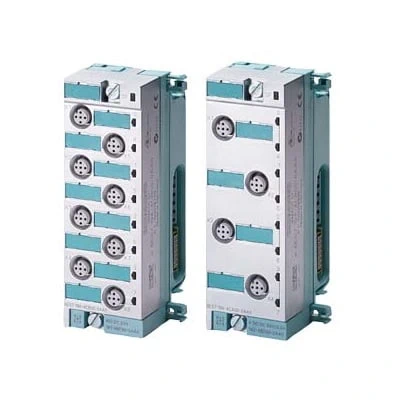
Digital expansion modules permit the connection of additional actuators and sensors to ET 200pro via integrated inputs/outputs.
| Article number | 6ES7141-4BF00-0AA0 | 6ES7141-4BF00-0AB0 | 6ES7141-4BH00-0AA0 |
| ET 200pro, EM 8DI 24V DC | ET 200pro, EM 8DI 24V DC HF | ET 200pro, EM 16DI DC 24V | |
| General information | |||
| Product function | |||
| ● Isochronous mode | No | No | No |
| Supply voltage | |||
| Rated value (DC) | 24 V | 24 V | 24 V |
| Reverse polarity protection | Yes; Against destruction; encoder power supply outputs applied with reversed polarity | Yes; against destruction; load increasing | Yes; Against destruction; encoder power supply outputs applied with reversed polarity |
| Input current | |||
| from supply voltage 1L+, max. | 20 mA | 40 mA | 30 mA |
| from backplane bus 3.3 V DC, max. | 20 mA | 20 mA | 20 mA |
| Encoder supply | |||
| Number of outputs | 8 | 8 | 8 |
| Short-circuit protection | Yes; per module, electronic | Yes; per channel, electronic | Yes; per module, electronic |
| Output current | |||
| ● up to 55 °C, max. | 1 A | 1 A | 1 A |
| Power loss | |||
| Power loss, typ. | 2.5 W | 2.5 W | 3 W |
| Address area | |||
| Address space per module | |||
| ● Address space per module, max. | 1 byte | 1 byte | 2 byte |
| Digital inputs | |||
| Number of digital inputs | 8 | 8 | 16 |
| Input characteristic curve in accordance with IEC 61131, type 1 | Yes | No | Yes |
| Input characteristic curve in accordance with IEC 61131, type 2 | No | Yes | |
| Number of simultaneously controllable inputs | |||
| all mounting positions | |||
| — up to 55 °C, max. | 8 | 8 | 16 |
| Input voltage | |||
| ● Rated value (DC) | 24 V | 24 V | 24 V |
| ● for signal “0” | -3 to +5V | -3 to +5V | -3 to +5V |
| ● for signal “1” | 13 to 30V | +11 to +30V | +11 to +30V |
| Input current | |||
| ● for signal “1”, typ. | 7 mA | 7 mA | 4 mA |
| Input delay (for rated value of input voltage) | |||
| for standard inputs | |||
| — parameterizable | No | Yes | No |
| — at “0” to “1”, min. | 1.2 ms | 0.5 ms; 0.5 ms/ 3ms/ 15 ms/ 20 ms | 1.2 ms |
| — at “0” to “1”, max. | 4.8 ms | 20 ms | 4.8 ms |
| — at “1” to “0”, min. | 1.2 ms | 0.5 ms; 0.5 ms/ 3ms/ 15 ms/ 20 ms | 0.7 ms |
| — at “1” to “0”, max. | 4.8 ms | 20 ms | 3 ms |
| Cable length | |||
| ● unshielded, max. | 30 m | 30 m | 30 m |
| Encoder | |||
| Connectable encoders | |||
| ● 2-wire sensor | Yes | Yes | Yes |
| — permissible quiescent current (2-wire sensor), max. | 1.5 mA | 1.5 mA | 1.5 mA |
| Interrupts/diagnostics/status information | |||
| Diagnostics function | Yes | Yes; channel by channel, parameterizable | Yes |
| Alarms | |||
| ● Diagnostic alarm | Yes | Yes | Yes |
| ● Hardware interrupt | Yes | ||
| Diagnoses | |||
| ● Diagnostic information readable | Yes | Yes | Yes |
| ● Wire-break | Yes; Monitoring, I < 0.3 mA; per channel | ||
| ● Short-circuit | Yes; Sensor supply to M; module by module | Yes; channel by channel | Yes; Sensor supply to M; module by module |
| Diagnostics indication LED | |||
| ● Group error SF (red) | Yes | Yes | Yes |
| ● Status indicator digital input (green) | Yes; Per channel | Yes; Per channel | Yes; Per channel |
| Potential separation | |||
| between backplane bus and all other circuit components | Yes | Yes | Yes |
| Potential separation digital inputs | |||
| ● between the channels | No | No | No |
| ● between the channels and backplane bus | Yes | Yes | Yes |
| Isolation | |||
| Isolation tested with | 707 V DC (type test) | 707 V DC (type test) | 707 V DC (type test) |
| Dimensions | |||
| Width | 45 mm | 45 mm | 45 mm |
| Height | 130 mm | 130 mm | 130 mm |
| Depth | 35 mm | 35 mm; without terminal module | 35 mm |
| Weights | |||
| Weight, approx. | 140 g | 140 g | 140 g |
| Article number | 6ES7142-4BD00-0AA0 | 6ES7142-4BD00-0AB0 | 6ES7142-4BF00-0AA0 |
| ET 200pro, EM 4DO 24V DC/2.0A | ET 200pro, EM 4DO 24VDC/2.0A HF | ET 200pro, EM 8DO DC24V/0.5A | |
| Supply voltage | |||
| Load voltage 2L+ | |||
| ● Rated value (DC) | 24 V | 24 V | 24 V |
| ● Short-circuit protection | Yes; per channel, electronic | Yes; per channel, electronic | Yes; per channel, electronic |
| ● Reverse polarity protection | Yes; against destruction; load increasing | Yes; against destruction; load increasing | Yes; against destruction; load increasing |
| Input current | |||
| from load voltage 2L+ (without load), max. | 20 mA | 40 mA | 30 mA |
| from backplane bus 3.3 V DC, max. | 20 mA | 30 mA | 30 mA |
| Power loss | |||
| Power loss, typ. | 2 W | 2.5 W | 2 W |
| Address area | |||
| Address space per module | |||
| ● Address space per module, max. | 1 byte | 1 byte | 1 byte |
| Digital outputs | |||
| Number of digital outputs | 4 | 4 | 8 |
| Short-circuit protection | Yes | Yes | Yes |
| ● Response threshold, typ. | 2.8 A | 2.8 A | 0.7 A |
| Limitation of inductive shutdown voltage to | 2L+ (-47 V) | 2L+ (-47 V) | 2L+ (-47 V) |
| Controlling a digital input | Yes | Yes | Yes; Isolation between 1L+ and 2L+ is no longer provided, as 1M and 2M are jumpered |
| Switching capacity of the outputs | |||
| ● on lamp load, max. | 10 W | 10 W | 5 W |
| Load resistance range | |||
| ● lower limit | 12 Ω | 12 Ω | 48 Ω |
| ● upper limit | 4 kΩ | 4 kΩ | 4 kΩ |
| Output voltage | |||
| ● for signal “1”, min. | 2L+ (-0,8 V) | 2L+ (-0,8 V) | 2L+ (-0,8 V) |
| Output current | |||
| ● for signal “1” rated value | 2 A | 2 A | 0.5 A |
| ● for signal “0” residual current, max. | 0.5 mA | 0.5 mA | 0.5 mA |
| Parallel switching of two outputs | |||
| ● for uprating | No | No | No |
| ● for redundant control of a load | Yes | Yes | Yes |
| Switching frequency | |||
| ● with resistive load, max. | 100 Hz | 100 Hz | 100 Hz |
| ● with inductive load, max. | 0.5 Hz | 0.5 Hz | 0.5 Hz |
| ● on lamp load, max. | 1 Hz | 1 Hz | 1 Hz |
| Total current of the outputs (per group) | |||
| all mounting positions | |||
| — up to 55 °C, max. | 4 A | 4 A | 4 A |
| Cable length | |||
| ● shielded, max. | 30 m | 30 m | 30 m |
| ● unshielded, max. | 30 m | 30 m | 30 m |
| Interrupts/diagnostics/status information | |||
| Diagnostics function | Yes | Yes | Yes |
| Substitute values connectable | Yes | ||
| Alarms | |||
| ● Diagnostic alarm | Yes | Yes | Yes |
| Diagnoses | |||
| ● Diagnostic information readable | Yes | Yes | Yes |
| ● Wire-break | Yes; channel by channel | ||
| ● Short-circuit | Yes; Short-circuit of outputs to ground; module by module | Yes; channel by channel | Yes; Short-circuit of outputs to ground; module by module |
| Diagnostics indication LED | |||
| ● Group error SF (red) | Yes | Yes | Yes |
| ● Status indicator digital output (green) | Yes | Yes | Yes |
| ● Channel fault indicator F (red) | Yes | ||
| Potential separation | |||
| between backplane bus and all other circuit components | Yes | Yes | Yes |
| Potential separation digital outputs | |||
| ● between the channels | No | No | No |
| ● between the channels and backplane bus | Yes | Yes | Yes |
| Isolation | |||
| Isolation tested with | 707 V DC (type test) | 707 V DC (type test) | 707 V DC (type test) |
| Standards, approvals, certificates | |||
| Suitable for safety-related tripping of standard modules | Yes | Yes | Yes |
| Highest safety class achievable for safety-related tripping of standard modules | |||
| ● Performance level according to ISO 13849-1 | PL d | PL d | PL d |
| ● Category according to ISO 13849-1 | Cat. 3 | Cat. 3 | Cat. 3 |
| ● SIL acc. to IEC 62061 | SIL 2 | SIL 2 | SIL 2 |
| Dimensions | |||
| Width | 45 mm | 45 mm | 45 mm |
| Height | 130 mm | 130 mm | 130 mm |
| Depth | 35 mm | 35 mm; without terminal module | 35 mm |
| Weights | |||
| Weight, approx. | 140 g | 140 g | 140 g |
| Article number | 6ES7143-4BF50-0AA0 | 6ES7143-4BF00-0AA0 |
| ET 200pro, EM 4DI / 4DO DC 24V, 0.5A | ET 200pro, EM 4 DIO / 4 DO DC 24V, 0.5A | |
| Supply voltage | ||
| Rated value (DC) | 24 V | |
| Reverse polarity protection | Yes; Against destruction; encoder power supply outputs applied with reversed polarity | |
| Load voltage 2L+ | ||
| ● Rated value (DC) | 24 V | 24 V |
| ● Short-circuit protection | Yes | Yes |
| ● Reverse polarity protection | Yes | Yes; against destruction; load increasing |
| Input current | ||
| from supply voltage 1L+, max. | 20 mA | |
| from load voltage 2L+ (without load), max. | 20 mA | 20 mA |
| from backplane bus 3.3 V DC, max. | 20 mA | 30 mA |
| Encoder supply | ||
| Short-circuit protection | Yes; per module, electronic | Yes; per module, electronic |
| Output current | ||
| ● up to 55 °C, max. | 1 A | 1 A |
| Power loss | ||
| Power loss, typ. | 2 W | 3 W |
| Digital inputs | ||
| Number of digital inputs | 4 | 4; 4 DIOs can be parameterized |
| Input characteristic curve in accordance with IEC 61131, type 3 | Yes | Yes |
| Number of simultaneously controllable inputs | ||
| all mounting positions | ||
| — up to 55 °C, max. | 4 | |
| Input voltage | ||
| ● Rated value (DC) | 24 V | 24 V |
| ● for signal “0” | -3 to +5V | -3 to +5V |
| ● for signal “1” | +11 to +30V | +11 to +30V |
| Input current | ||
| ● for signal “1”, typ. | 7 mA | 7 mA |
| Input delay (for rated value of input voltage) | ||
| for standard inputs | ||
| — at “0” to “1”, min. | 1.2 ms | |
| — at “0” to “1”, max. | 3 ms | 4.8 ms |
| — at “1” to “0”, min. | 1.2 ms | |
| — at “1” to “0”, max. | 3 ms | 4.8 ms |
| Cable length | ||
| ● unshielded, max. | 30 m | 30 m |
| Digital outputs | ||
| Number of digital outputs | 4 | 8; 4 DO fixed, 4 DIO parameterizable |
| ● in groups of | 4; 2 load groups for 4 outputs each | |
| Short-circuit protection | Yes; per channel, electronic | Yes; per channel, electronic |
| ● Response threshold, typ. | 0.7 A | 0.7 A |
| Limitation of inductive shutdown voltage to | Typ. (2L+) -47 V | Typ. (L1+, L2+) -47 V |
| Controlling a digital input | Yes | Yes |
| Switching capacity of the outputs | ||
| ● on lamp load, max. | 5 W | 5 W |
| Load resistance range | ||
| ● lower limit | 48 Ω | 48 Ω |
| ● upper limit | 4 kΩ | 4 kΩ |
| Output voltage | ||
| ● for signal “1”, min. | 2L+ (-0,8 V) | |
| Output current | ||
| ● for signal “1” rated value | 0.5 A | 0.5 A |
| ● for signal “0” residual current, max. | 0.5 mA | 0.5 mA |
| Parallel switching of two outputs | ||
| ● for uprating | No | No |
| ● for redundant control of a load | Yes | Yes |
| Switching frequency | ||
| ● with resistive load, max. | 100 Hz | 100 Hz |
| ● with inductive load, max. | 0.5 Hz | 0.5 Hz |
| ● on lamp load, max. | 1 Hz | 1 Hz |
| Total current of the outputs (per group) | ||
| all mounting positions | ||
| — up to 55 °C, max. | 2 A | 2 A |
| Cable length | ||
| ● unshielded, max. | 30 m | 30 m |
| Encoder | ||
| Connectable encoders | ||
| ● 2-wire sensor | Yes | Yes |
| — permissible quiescent current (2-wire sensor), max. | 1.5 mA | 1.5 mA |
| Interrupts/diagnostics/status information | ||
| Diagnostics function | Yes | Yes |
| Alarms | ||
| ● Diagnostic alarm | Yes | Yes |
| Diagnoses | ||
| ● Diagnostic information readable | Yes | Yes |
| ● Short-circuit | Yes; Short-circuit of outputs to ground; module by module | Yes; Short-circuit of outputs to ground; module by module |
| Diagnostics indication LED | ||
| ● Group error SF (red) | Yes | |
| ● Status indicator digital input (green) | Yes | Yes |
| ● Status indicator digital output (green) | Yes | Yes |
| Potential separation | ||
| between backplane bus and all other circuit components | Yes | Yes |
| Potential separation digital inputs | ||
| ● between the channels | No | No |
| ● between the channels and backplane bus | Yes | Yes |
| Potential separation digital outputs | ||
| ● between the channels | No | |
| ● between the channels and backplane bus | Yes | Yes |
| Isolation | ||
| Isolation tested with | 707 V DC (type test) | 707 V DC (type test) |
| Standards, approvals, certificates | ||
| Suitable for safety-related tripping of standard modules | Yes | |
| Highest safety class achievable for safety-related tripping of standard modules | ||
| ● Performance level according to ISO 13849-1 | PL d | |
| ● Category according to ISO 13849-1 | Cat. 3 | |
| ● SIL acc. to IEC 62061 | SIL 2 | |
| Dimensions | ||
| Width | 45 mm | 45 mm |
| Height | 130 mm | 130 mm |
| Depth | 35 mm | 35 mm |
| Weights | ||
| Weight, approx. | 140 g | 140 g |