| Article number | 6ES7138-4CF03-0AB0 | 6ES7138-4CF42-0AB0 |
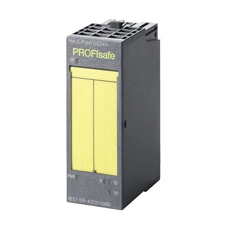
| ET200S, Powermod. PM-E F PM, DC24V | ET200S, Powermod. PM-E F PP, DC24V | |
| Supply voltage | ||
| Load voltage L+ | ||
| ● Rated value (DC) | 24 V | 24 V |
| ● Reverse polarity protection | No | No |
| Input current | ||
| From load voltage L+ (no load), typ. | 100 mA | 100 mA |
| from backplane bus 24 V DC, max. | 28 mA | 28 mA |
| Power loss | ||
| Power loss, typ. | 4 W | 4 W |
| Address area | ||
| Address space per module | ||
| ● Inputs | 5 byte | 5 byte |
| ● Outputs | 5 byte | 5 byte |
| Digital outputs | ||
| Number of digital outputs | 2 | 1; Relays |
| Short-circuit protection | Yes; Electronic | No |
| ● Response threshold, typ. | Response threshold (short-circuit): 5 to 12 A; response threshold (external short-circuit to ground): 5 to 12 A; response threshold (external short-circuit to P potential): 25 to 45 A | |
| Limitation of inductive shutdown voltage to | L+ (-2x 47 V) | |
| Controlling a digital input | No | Yes |
| Switching capacity of the outputs | ||
| ● on lamp load, max. | 10 W | 100 W |
| Load resistance range | ||
| ● lower limit | 12 Ω | |
| ● upper limit | 1 kΩ | |
| Output voltage | ||
| ● for signal “1”, min. | L+ (-2,0 V), current sourcing switch: L+ (-1,5 V), voltage drop on current sinking switch: max. 0.5 V | |
| Output current | ||
| ● for signal “1” rated value | 2 A | |
| ● for signal “1” permissible range for 0 to 60 °C, min. | 20 mA | |
| ● for signal “1” permissible range for 0 to 60 °C, max. | 2.4 A | |
| ● for signal “0” residual current, max. | 0.5 mA | |
| Parallel switching of two outputs | ||
| ● for uprating | No | |
| ● for redundant control of a load | No | |
| Switching frequency | ||
| ● with resistive load, max. | 30 Hz | 2 Hz |
| ● with inductive load, max. | 0.1 Hz | 0.1 Hz; with inductive load to IEC 60947-5-1, DC-13 / AC-15 |
| ● on lamp load, max. | 10 Hz | 2 Hz |
| Total current of the outputs (per group) | ||
| horizontal installation | ||
| — up to 40 °C, max. | 10 A | 10 A |
| — up to 55 °C, max. | 7 A | 8 A |
| — up to 60 °C, max. | 6 A | 7 A |
| vertical installation | ||
| — up to 40 °C, max. | 6 A | 8 A |
| Relay outputs | ||
| Switching capacity of contacts | ||
| — with resistive load, up to 50 °C, max. | 10 A | 10 A |
| Cable length | ||
| ● shielded, max. | 200 m | |
| ● unshielded, max. | 200 m | |
| Interrupts/diagnostics/status information | ||
| Diagnostics function | Yes | Yes |
| Diagnoses | ||
| ● Diagnostic information readable | Yes | Yes |
| ● Wire-break | Yes | No |
| ● Short-circuit | Yes | Yes |
| ● missing load voltage | Yes | Yes |
| Diagnostics indication LED | ||
| ● Rated load voltage PWR (green) | Yes | Yes |
| ● Group error SF (red) | Yes | Yes |
| ● Status indicator digital output (green) | Yes | Yes |
| Potential separation | ||
| Potential separation digital outputs | ||
| ● between the channels | No | No |
| ● between the channels and backplane bus | Yes | Yes |
| ● Between the channels and load voltage L+ | No | No |
| Isolation | ||
| Isolation tested with | 500 V DC | 500 V DC |
| Standards, approvals, certificates | ||
| Highest safety class achievable in safety mode | ||
| ● acc. to EN 954 | 4 | 4 |
| ● Performance level according to ISO 13849-1 | e | e |
| ● SIL acc. to IEC 61508 | Up to SIL 3 | With Std-DO: Max. SIL 2, without Std-DO max. SIL 3 depending on configuration |
| Dimensions | ||
| Width | 30 mm | 30 mm |
| Height | 81 mm | 81 mm |
| Depth | 52 mm | 52 mm |
| Weights | ||
| Weight, approx. | 88 g | 80 g |