Using fail-safe ET 200MP/S7-1500 modules makes it possible to implement safety-related application requirements as an integral part of the overall automation. The safety functions required for fail-safe operation are integrated in the modules. Communication with the fail-safe SIMATIC S7 CPUs is performed by means of PROFIsafe.
The modules can be operated both in centralized and distributed configurations.
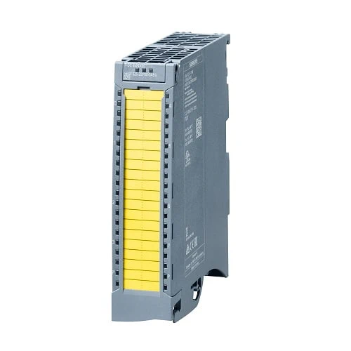
| Article number | 6ES7526-2BF00-0AB0 | |
| ET 200MP, F-DQ 8x24VDC 2A PPM | ||
| General information | ||
| Product type designation | F-DQ 8x24VDC/2A PPM | |
| Firmware version | ||
| ● FW update possible | Yes | |
| Product function | ||
| ● I&M data | Yes; I&M0 to I&M3 | |
| Engineering with | ||
| ● STEP 7 TIA Portal configurable/integrated from version | V13 SP1 with HSP 0086 | |
| Operating mode | ||
| ● DQ | Yes | |
| Supply voltage | ||
| Rated value (DC) | 24 V | |
| permissible range, lower limit (DC) | 19.2 V | |
| permissible range, upper limit (DC) | 28.8 V | |
| Reverse polarity protection | Yes | |
| Input current | ||
| Current consumption (rated value) | 110 mA; without load | |
| Current consumption, max. | 130 mA; without load | |
| output voltage / header | ||
| Rated value (DC) | 24 V | |
| Power | ||
| Power available from the backplane bus | 0.8 W | |
| Power loss | ||
| Power loss, typ. | 11 W | |
| Address area | ||
| Address space per module | ||
| ● Inputs | 6 byte; S7-300/400F CPU, 5 byte | |
| ● Outputs | 6 byte; S7-300/400F CPU, 5 byte | |
| Hardware configuration | ||
| Automatic encoding | Yes | |
| ● Electronic coding element type F | Yes | |
| Digital outputs | ||
| Number of digital outputs | 8 | |
| Current-sinking | Yes | |
| Current-sourcing | Yes | |
| Short-circuit protection | Yes | |
| Open-circuit detection | Yes | |
| ● Response threshold, typ. | 8 mA | |
| Overload protection | Yes | |
| ● Response threshold, typ. | 2.9 A | |
| Limitation of inductive shutdown voltage to | PM-switching: -24 V + (-47 V), PP-switching: -24 V | |
| Switching capacity of the outputs | ||
| ● with resistive load, max. | 2 A | |
| ● on lamp load, max. | 10 W | |
| Load resistance range | ||
| ● lower limit | 12 Ω | |
| ● upper limit | 2 000 Ω | |
| Output voltage | ||
| ● for signal “1”, min. | 24 V; L+ (-0.5 V) | |
| Output current | ||
| ● for signal “1” rated value | 2 A | |
| ● for signal “0” residual current, max. | 0.5 mA; Current-sourcing, or current sourcing and sinking switches individually, current sinking: max. 1 mA | |
| Switching frequency | ||
| ● with resistive load, max. | 30 Hz | |
| ● with inductive load, max. | 0.1 Hz | |
| ● on lamp load, max. | 10 Hz | |
| Total current of the outputs | ||
| ● Current per channel, max. | 2 A | |
| Total current of the outputs (per module) | ||
| horizontal installation | ||
| — up to 40 °C, max. | 16 A | |
| — up to 60 °C, max. | 8 A | |
| vertical installation | ||
| — up to 40 °C, max. | 8 A | |
| Cable length | ||
| ● shielded, max. | 1 000 m | |
| ● unshielded, max. | 500 m | |
| Interrupts/diagnostics/status information | ||
| Diagnostics function | Yes | |
| Substitute values connectable | No | |
| Alarms | ||
| ● Diagnostic alarm | Yes | |
| Diagnoses | ||
| ● Monitoring the supply voltage | Yes | |
| ● Wire-break | Yes | |
| ● Short-circuit | Yes | |
| ● Group error | Yes | |
| Diagnostics indication LED | ||
| ● RUN LED | Yes; green LED | |
| ● ERROR LED | Yes; red LED | |
| ● Monitoring of the supply voltage (PWR-LED) | Yes | |
| ● Channel status display | Yes; green LED | |
| ● for channel diagnostics | Yes; red LED | |
| ● for module diagnostics | Yes; red LED | |
| Potential separation | ||
| Potential separation channels | ||
| ● between the channels | No | |
| ● between the channels and backplane bus | Yes | |
| Isolation | ||
| Isolation tested with | 707 V DC (type test) | |
| Standards, approvals, certificates | ||
| Suitable for safety functions | Yes | |
| Highest safety class achievable in safety mode | ||
| ● Performance level according to ISO 13849-1 | PLe | |
| ● SIL acc. to IEC 61508 | SIL 3 | |
| Probability of failure (for service life of 20 years and repair time of 100 hours) | ||
| — Low demand mode: PFDavg in accordance with SIL3 | < 6.00E-05 | |
| — High demand/continuous mode: PFH in accordance with SIL3 | < 2.00E-09 1/h | |
| Ambient conditions | ||
| Ambient temperature during operation | ||
| ● horizontal installation, min. | 0 °C | |
| ● horizontal installation, max. | 60 °C | |
| ● vertical installation, min. | 0 °C | |
| ● vertical installation, max. | 40 °C | |
| Dimensions | ||
| Width | 35 mm | |
| Height | 147 mm | |
| Depth | 129 mm | |
| Weights | ||
| Weight, approx. | 300 g | |