Fail-safe digital input modules are suitable for connecting
The modules are implemented centrally with SIMATIC S7-31xF-2 DP, and in the ET 200M distributed I/O module in combination with SIMATIC IM 151-7 F-CPU, S7-31xF-2 DP, S7-416F-2 and S7-400F/FH. They can also be used in non-safety-relevant standard mode. In this case, they behave like standard S7-300 modules.
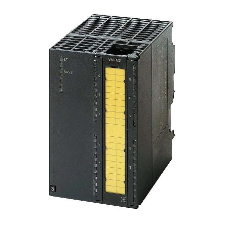
| Article number | 6ES7326-1BK02-0AB0 |
| SM326, F-DI 24 X DC24V, failsafe | |
| Supply voltage | |
| Rated value (DC) | 24 V |
| Reverse polarity protection | Yes |
| Input current | |
| from load voltage L+ (without load), max. | 450 mA |
| from backplane bus 5 V DC, max. | 100 mA |
| Encoder supply | |
| Number of outputs | 4; Isolated |
| Type of output voltage | |
| Output current | |
| ● Rated value | 400 mA |
| Power loss | |
| Power loss, typ. | 10 W |
| Digital inputs | |
| Number of digital inputs | 24 |
| Number of simultaneously controllable inputs | |
| all mounting positions | |
| — up to 40 °C, max. | 24 |
| — up to 60 °C, max. | 24; (at 24 V) or 18 (at 28.8 V) |
| Input voltage | |
| ● Type of input voltage | DC |
| ● Rated value (DC) | 24 V |
| ● for signal “0” | -30 to +5 V |
| ● for signal “1” | +11 to +30V |
| Input current | |
| ● for signal “0”, max. (permissible quiescent current) | 2 mA |
| ● for signal “1”, typ. | 10 mA |
| Input delay (for rated value of input voltage) | |
| for standard inputs | |
| — at “0” to “1”, max. | 3.4 ms |
| — at “1” to “0”, max. | 3.4 ms |
| for NAMUR inputs | |
| — at “0” to “1”, max. | |
| — at “1” to “0”, max. | |
| Cable length | |
| ● shielded, max. | 200 m |
| ● unshielded, max. | 100 m |
| Encoder | |
| Connectable encoders | |
| ● 2-wire sensor | Yes; if short-circuit test is deactivated |
| — permissible quiescent current (2-wire sensor), max. | 2 mA |
| Interrupts/diagnostics/status information | |
| Diagnostics function | Yes |
| Alarms | |
| ● Diagnostic alarm | Yes |
| Diagnoses | |
| ● Diagnostic information readable | Yes |
| Diagnostics indication LED | |
| ● Fail-safe operation | Yes |
| ● Group error SF (red) | Yes |
| Ex(i) characteristics | |
| Module for Ex(i) protection | |
| maximum values for connecting terminals for gas group IIC | |
| ● Uo (no-load voltage), max. | |
| ● Io (short-circuit current), max. | |
| ● Po (power output), max. | |
| ● Co (permissible external capacity), max. | |
| ● Lo (permissible external inductivity), max. | |
| ● Um (voltage at non-intrinsically safe connecting terminals), max. | |
| Potential separation | |
| Potential separation digital inputs | |
| ● between the channels | Yes |
| ● between the channels, in groups of | 12 |
| ● between the channels and backplane bus | Yes |
| ● between the channels and the power supply of the electronics | |
| Isolation | |
| Isolation tested with | 500 V DC/350 V AC |
| Standards, approvals, certificates | |
| Highest safety class achievable in safety mode | |
| ● acc. to DIN VDE 0801 | AK 6 |
| ● acc. to EN 954 | Cat. 4 |
| ● Performance level according to ISO 13849-1 | e |
| ● SIL acc. to IEC 61508 | SIL 3 |
| Use in hazardous areas | |
| ● ATEX certificate | |
| Ambient conditions | |
| Ambient temperature during operation | |
| ● max. | |
| connection method / header | |
| required front connector | 40-pin |
| Dimensions | |
| Width | 80 mm |
| Height | 125 mm |
| Depth | 120 mm |
| Weights | |
| Weight, approx. | 442 g |