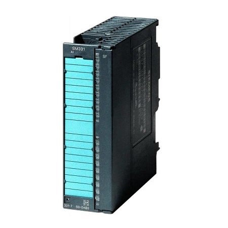
Ex analog input modules are used for the connection of intrinsically-safe analog equipment from the Ex field.
| Article number | 6ES7331-7RD00-0AB0 | 6ES7331-7SF00-0AB0 |
| SIMATIC S7, SM 331 ANALOG INPUT | SIMATIC S7, SM 331 ANALOG INPUT | |
| Supply voltage | ||
| Load voltage L+ | ||
| ● Rated value (DC) | 24 V | 24 V |
| ● Reverse polarity protection | Yes | |
| Input current | ||
| from load voltage L+ (without load), max. | 250 mA | |
| from backplane bus 5 V DC, max. | 60 mA | 120 mA |
| output voltage / header | ||
| supply voltage of the transmitters / header | ||
| ● supply voltage / of the transmitters / at DC / rated value | 13 V; at 22 mA | |
| Power loss | ||
| Power loss, typ. | 3 W | 0.6 W |
| Analog inputs | ||
| Number of analog inputs | 4 | 8; 8x thermocouples; 4x RTD thermoresistors |
| permissible input current for current input (destruction limit), max. | 40 mA | |
| Input ranges | ||
| ● Voltage | No | Yes |
| ● Current | Yes | No |
| ● Thermocouple | No | Yes |
| ● Resistance thermometer | No | Yes |
| ● Resistance | No | Yes |
| Input ranges (rated values), voltages | ||
| ● -1 V to +1 V | Yes | |
| — Input resistance (-1 V to +1 V) | 10 MΩ | |
| ● -25 mV to +25 mV | Yes | |
| — Input resistance (-25 mV to +25 mV) | 10 MΩ | |
| ● -250 mV to +250 mV | Yes | |
| — Input resistance (-250 mV to +250 mV) | 10 MΩ | |
| ● -50 mV to +50 mV | Yes | |
| — Input resistance (-50 mV to +50 mV) | 10 MΩ | |
| ● -500 mV to +500 mV | Yes | |
| — Input resistance (-500 mV to +500 mV) | 10 MΩ | |
| ● -80 mV to +80 mV | Yes | |
| — Input resistance (-80 mV to +80 mV) | 10 MΩ | |
| Input ranges (rated values), currents | ||
| ● 0 to 20 mA | Yes | |
| — Input resistance (0 to 20 mA) | 50 Ω | |
| ● 4 mA to 20 mA | Yes | |
| — Input resistance (4 mA to 20 mA) | 50 Ω | |
| Input ranges (rated values), thermocouples | ||
| ● Type B | Yes | |
| — Input resistance (Type B) | 10 MΩ | |
| ● Type E | Yes | |
| — Input resistance (Type E) | 10 MΩ | |
| ● Type J | Yes | |
| — Input resistance (type J) | 10 MΩ | |
| ● Type K | Yes | |
| — Input resistance (Type K) | 10 MΩ | |
| ● Type L | Yes | |
| — Input resistance (Type L) | 10 MΩ | |
| ● Type N | Yes | |
| — Input resistance (Type N) | 10 MΩ | |
| ● Type R | Yes | |
| — Input resistance (Type R) | 10 MΩ | |
| ● Type S | Yes | |
| — Input resistance (Type S) | 10 MΩ | |
| ● Type T | Yes | |
| — Input resistance (Type T) | 10 MΩ | |
| ● Type U | Yes | |
| — Input resistance (Type U) | 10 MΩ | |
| Input ranges (rated values), resistance thermometer | ||
| ● Ni 100 | Yes | |
| — Input resistance (Ni 100) | 10 MΩ | |
| ● Pt 100 | Yes | |
| — Input resistance (Pt 100) | 10 MΩ | |
| ● Pt 200 | Yes | |
| — Input resistance (Pt 200) | 10 MΩ | |
| Cable length | ||
| ● shielded, max. | 200 m | 200 m; TC: 50 m |
| Analog value generation for the inputs | ||
| Integration and conversion time/resolution per channel | ||
| ● Resolution with overrange (bit including sign), max. | 16 bit; 10 bit to 15 bit + sign | 16 bit; 10 bit to 15 bit + sign |
| ● Integration time, parameterizable | Yes; 2.5 to 100 ms | Yes; 2.5 to 100 ms |
| ● Interference voltage suppression for interference frequency f1 in Hz | 10 to 400 Hz | 10 to 400 Hz |
| Encoder | ||
| Connection of signal encoders | ||
| ● for current measurement as 2-wire transducer | Yes | Yes |
| ● for current measurement as 4-wire transducer | Yes | Yes |
| Errors/accuracies | ||
| Operational error limit in overall temperature range | ||
| ● Current, relative to input range, (+/-) | 0.45 % | |
| ● Resistance thermometer, relative to input range, (+/-) | 0.04 %; 0.09 to 0.04% | |
| Basic error limit (operational limit at 25 °C) | ||
| ● Current, relative to input range, (+/-) | 0.1 % | |
| ● Resistance thermometer, relative to input range, (+/-) | 0.008 %; 0.018 … 0.008% | |
| Interrupts/diagnostics/status information | ||
| Diagnostics function | Yes | Yes |
| Diagnoses | ||
| ● Diagnostic information readable | Yes | Yes |
| ● Overrange | Yes | Yes |
| ● Wire-break in signal transmitter cable | Yes | Yes |
| ● Short-circuit of the signal encoder cable | Yes | Yes |
| Diagnostics indication LED | ||
| ● Group error SF (red) | Yes | Yes |
| ● Channel fault indicator F (red) | Yes | Yes |
| Ex(i) characteristics | ||
| Module for Ex(i) protection | Yes | Yes |
| maximum values for connecting terminals for gas group IIC | ||
| ● Uo (no-load voltage), max. | 25.2 V | 5.9 V |
| ● Io (short-circuit current), max. | 68.5 mA | 28.8 mA |
| ● Po (power output), max. | 431 mW | 41.4 mW |
| ● Co (permissible external capacity), max. | 90 nF | 43 µF |
| ● Lo (permissible external inductivity), max. | 7.5 mH | 40 mH |
| Potential separation | ||
| Potential separation analog inputs | ||
| ● between the channels | Yes | No |
| ● between the channels and backplane bus | Yes | Yes |
| Standards, approvals, certificates | ||
| Use in hazardous areas | ||
| ● ATEX marking | ATEX II 3 G (2) GD Ex nA [ib Gb] [ib IIIC Db] IIC T4 Gc | ATEX II 3 G (2) GD Ex nA [ib Gb] [ib IIIC Db] IIC T4 Gc |
| ● FM marking | Class I, Division 2, Group A, B, C, D T4 | Class I, Division 2, Group A, B, C, D T4 |
| ● Test number PTB | Ex-96.D.2092X | Ex-96.D.2108X |
| Ambient conditions | ||
| Ambient temperature during operation | ||
| ● max. | 60 °C | 60 °C |
| connection method / header | ||
| required front connector | 20-pin | 20-pin |
| Dimensions | ||
| Width | 40 mm | |
| Height | 125 mm | |
| Depth | 120 mm | |
| Weights | ||
| Weight, approx. | 290 g | 210 g |