The SM 1223 digital input/output signal modules convert:
| Article number | 6ES7223-1BH32-0XB0 | 6ES7223-1BL32-0XB0 | 6ES7223-1BL32-1XB0 | 6ES7223-1PH32-0XB0 | 6ES7223-1PL32-0XB0 | 6ES7223-1QH32-0XB0 |
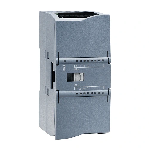
| Digital I/O SM 1223, 8 DI / 8 DO | Digital I/O SM 1223, 16DI/16DO | Digital I/O SM 1223, 16DI/16DO sink | Digital I/O SM 1223, 8DI/8DO | Digital I/O SM 1223, 16DI/16DO | Digital I/O SM 1223, 8DI AC/ 8DO Rly | |
| General information | ||||||
| Product type designation | SM 1223, DI 8×24 V DC, DQ 8×24 V DC | SM 1223, DI 16×24 V DC, DQ 16×24 V DC | SM 1223, DI 16×24 V DC, DO 16x 24 V DC Sink | SM 1223, DI 8×24 V DC, DQ 8x relay | SM 1223, DI 16×24 V DC, DQ 16x relay | SM 1223, DI 8×120/230 V AC, DQ 8x relay |
| Supply voltage | ||||||
| Rated value (DC) | 24 V | 24 V | 24 V | 24 V | 24 V | 24 V |
| permissible range, lower limit (DC) | 20.4 V | 20.4 V | 20.4 V | 20.4 V | 20.4 V | 20.4 V |
| permissible range, upper limit (DC) | 28.8 V | 28.8 V | 28.8 V | 28.8 V | 28.8 V | 28.8 V |
| Input current | ||||||
| from backplane bus 5 V DC, max. | 145 mA | 185 mA | 185 mA | 145 mA | 180 mA | 120 mA |
| Digital inputs | ||||||
| ● from load voltage L+ (without load), max. | 4 mA; per channel | 4 mA; per channel | 4 mA; per channel | 4 mA/input 11 mA/relay | 4 mA/input 11 mA/relay | |
| output voltage / header | ||||||
| supply voltage of the transmitters / header | ||||||
| ● product function / supply voltage for transmitters | Yes | Yes | Yes | Yes | Yes | Yes |
| Power loss | ||||||
| Power loss, typ. | 2.5 W | 4.5 W | 4.5 W | 5.5 W | 10 W | 7.5 W |
| Digital inputs | ||||||
| Number of digital inputs | 8 | 16 | 16 | 8 | 16 | 8 |
| ● in groups of | 2 | 2 | 2 | 2 | 2 | 4 |
| Input characteristic curve in accordance with IEC 61131, type 1 | Yes | Yes | Yes | Yes | Yes | Yes |
| Number of simultaneously controllable inputs | ||||||
| all mounting positions | ||||||
| — up to 40 °C, max. | 8 | 16 | 16 | 8 | 16 | 8 |
| horizontal installation | ||||||
| — up to 40 °C, max. | 8 | 16 | 16 | 8 | 16 | 8 |
| — up to 50 °C, max. | 8 | 16 | 16 | 8 | 16 | 8 |
| vertical installation | ||||||
| — up to 40 °C, max. | 8 | 16 | 16 | 8 | 16 | 8 |
| Input voltage | ||||||
| ● Type of input voltage | DC | DC | DC | DC | DC | AC |
| ● Rated value (DC) | 24 V | 24 V | 24 V | 24 V | 24 V | |
| ● Rated value (AC) | 120/230 V AC | |||||
| ● for signal “0” | 5 V DC at 1 mA | 5 V DC at 1 mA | 5 V DC at 1 mA | 5 V DC at 1 mA | 5 V DC at 1 mA | 20 V AC at 1 mA |
| ● for signal “1” | 15 V DC at 2.5 mA | 15 V DC at 2.5 mA | 15 V DC at 2.5 mA | 15 V DC at 2.5 mA | 15 V DC at 2.5 mA | 79 V AC at 2.5 mA |
| Input current | ||||||
| ● for signal “0”, max. (permissible quiescent current) | 1 mA | 1 mA | 1 mA | 1 mA | 1 mA | 1 mA |
| ● for signal “1”, min. | 2.5 mA | 2.5 mA | 2.5 mA | 2.5 mA | 2.5 mA | 2.5 mA |
| ● for signal “1”, typ. | 4 mA | 4 mA | 4 mA | 4 mA | 4 mA | 9 mA |
| Input delay (for rated value of input voltage) | ||||||
| for standard inputs | ||||||
| — parameterizable | Yes; 0.2 ms, 0.4 ms, 0.8 ms, 1.6 ms, 3.2 ms, 6.4 ms and 12.8 ms, selectable in groups of four | Yes; 0.2 ms, 0.4 ms, 0.8 ms, 1.6 ms, 3.2 ms, 6.4 ms and 12.8 ms, selectable in groups of four | Yes; 0.2 ms, 0.4 ms, 0.8 ms, 1.6 ms, 3.2 ms, 6.4 ms and 12.8 ms, selectable in groups of four | Yes; 0.2 ms, 0.4 ms, 0.8 ms, 1.6 ms, 3.2 ms, 6.4 ms and 12.8 ms, selectable in groups of four | Yes; 0.2 ms, 0.4 ms, 0.8 ms, 1.6 ms, 3.2 ms, 6.4 ms and 12.8 ms, selectable in groups of four | Yes; 0.2 ms, 0.4 ms, 0.8 ms, 1.6 ms, 3.2 ms, 6.4 ms and 12.8 ms, selectable in groups of four |
| for interrupt inputs | ||||||
| — parameterizable | Yes | Yes | Yes | Yes | Yes | Yes |
| Cable length | ||||||
| ● shielded, max. | 500 m | 500 m | 500 m | 500 m | 500 m | 500 m |
| ● unshielded, max. | 300 m | 300 m | 300 m | 300 m | 300 m | 300 m |
| Digital outputs | ||||||
| Number of digital outputs | 8 | 16 | 16; Transistor current sinking | 8 | 16 | 8 |
| ● in groups of | 1 | 1 | 1 | 2 | 4 | 4 |
| Short-circuit protection | No; to be provided externally | No; to be provided externally | Yes; 1 to 3.5 A | No; to be provided externally | No; to be provided externally | No; to be provided externally |
| Limitation of inductive shutdown voltage to | L+ (-48 V) | L+ (-48 V) | Typ 45 V | |||
| Switching capacity of the outputs | ||||||
| ● with resistive load, max. | 0.5 A | 0.5 A | 0.5 A | 2 A | 2 A | 2 A |
| ● on lamp load, max. | 5 W | 5 W | 5 W | 30 W with DC, 200 W with AC | 30 W with DC, 200 W with AC | 30 W with DC, 200 W with AC |
| Output voltage | ||||||
| ● Rated value (DC) | 24 V | 24 V | 24 V | 5 V DC to 30 V DC | 5 V DC to 30 V DC | 5 V DC to 30 V DC |
| ● Rated value (AC) | 5 V AC to 250 V AC | 5 V AC to 250 V AC | 5 V AC to 250 V AC | |||
| ● for signal “0”, max. | 0.1 V; with 10 kOhm load | 0.1 V; with 10 kOhm load | L+ minus 0.75 V DC with 10k Load | |||
| ● for signal “1”, min. | 20 V DC | 20 V DC | 0,5 V | |||
| Output current | ||||||
| ● for signal “1” rated value | 0.5 A | 0.5 A | 0.5 A | 2 A | 2 A | 2 A |
| ● for signal “1” permissible range, max. | 0.5 A | 0.5 A | 0.5 A | 2 A | 2 A | 2 A |
| ● for signal “0” residual current, max. | 10 µA | 10 µA | 75 µA | |||
| Output delay with resistive load | ||||||
| ● “0” to “1”, max. | 50 µs | 50 µs | 20 µs | 10 ms | 10 ms | 10 ms |
| ● “1” to “0”, max. | 200 µs | 200 µs | 350 µs | 10 ms | 10 ms | 10 ms |
| Total current of the outputs (per group) | ||||||
| horizontal installation | ||||||
| — up to 50 °C, max. | 4 A; Current per mass | 8 A; Current per mass | 8 A; Current per mass | 10 A; Current per mass | 8 A; Current per mass | 8 A; Current per mass |
| Relay outputs | ||||||
| ● Number of relay outputs | 8 | 16 | 8 | |||
| ● Rated supply voltage of relay coil L+ (DC) | 24 V | 24 V | 24 V | |||
| ● Number of operating cycles, max. | mechanically 10 million, at rated load voltage 100 000 | mechanically 10 million, at rated load voltage 100 000 | mechanically 10 million, at rated load voltage 100 000 | |||
| Switching capacity of contacts | ||||||
| — with inductive load, max. | 0.5 A | 0.5 A | 2 A | 2 A | 2 A | |
| — on lamp load, max. | 5 W | 5 W | 30 W with DC, 200 W with AC | 30 W with DC, 200 W with AC | 30 W with DC, 200 W with AC | |
| — with resistive load, max. | 0.5 A | 0.5 A | 2 A | 2 A | 2 A | |
| Cable length | ||||||
| ● shielded, max. | 500 m | 500 m | 500 m | 500 m | 500 m | 500 m |
| ● unshielded, max. | 150 m | 150 m | 150 m | 150 m | 150 m | 150 m |
| Interrupts/diagnostics/status information | ||||||
| Alarms | ||||||
| ● Diagnostic alarm | Yes | Yes | Yes | Yes | Yes | Yes |
| Diagnostics indication LED | ||||||
| ● for status of the inputs | Yes | Yes | Yes | Yes | Yes | Yes |
| ● for status of the outputs | Yes | Yes | Yes | Yes | Yes | Yes |
| Potential separation | ||||||
| Potential separation digital inputs | ||||||
| ● between the channels, in groups of | 2 | 2 | 2 | 2 | 2 | 2 |
| Potential separation digital outputs | ||||||
| ● between the channels | Relays | Relays | Relays | |||
| ● between the channels, in groups of | 1 | 1 | 1 | 2 | 4 | 2 |
| ● between the channels and backplane bus | 500 V AC | 500 V AC | 500 V AC | 1 500 V AC for 1 minute | 1 500 V AC for 1 minute | 1 500 V AC for 1 minute |
| Permissible potential difference | ||||||
| between different circuits | 750 V AC for 1 minute | 750 V AC for 1 minute | 750 V AC for 1 minute | |||
| Degree and class of protection | ||||||
| IP degree of protection | IP20 | IP20 | IP20 | IP20 | IP20 | IP20 |
| Standards, approvals, certificates | ||||||
| CE mark | Yes | Yes | Yes | Yes | Yes | Yes |
| CSA approval | Yes | Yes | Yes | Yes | Yes | Yes |
| UL approval | Yes | Yes | Yes | Yes | Yes | Yes |
| cULus | Yes | Yes | Yes | Yes | Yes | Yes |
| FM approval | Yes | Yes | Yes | Yes | Yes | Yes |
| RCM (formerly C-TICK) | Yes | Yes | Yes | Yes | Yes | Yes |
| KC approval | Yes | Yes | Yes | Yes | Yes | Yes |
| Marine approval | Yes | Yes | Yes | Yes | Yes | Yes |
| Ambient conditions | ||||||
| Free fall | ||||||
| ● Fall height, max. | 0.3 m; five times, in product package | 0.3 m; five times, in product package | 0.3 m; five times, in product package | 0.3 m; five times, in product package | 0.3 m; five times, in product package | 0.3 m; five times, in product package |
| Ambient temperature during operation | ||||||
| ● min. | -20 °C | -20 °C | -20 °C | -20 °C | -20 °C | -20 °C |
| ● max. | 60 °C | 60 °C | 60 °C | 60 °C | 60 °C; Number of simultaneously activated outputs: 8 (no adjacent points) at 60 °C horizontal or 50 °C vertical, 16 at 55 °C horizontal or 45 °C vertical | 60 °C; Number of simultaneously activated outputs: 4 (no adjacent points) at 60 °C horizontal or 50 °C vertical, 8 at 55 °C horizontal or 45 °C vertical |
| ● horizontal installation, min. | -20 °C | -20 °C | -20 °C | -20 °C | -20 °C | -20 °C |
| ● horizontal installation, max. | 60 °C | 60 °C | 60 °C | 60 °C | 60 °C | 60 °C |
| ● vertical installation, min. | -20 °C | -20 °C | -20 °C | -20 °C | -20 °C | -20 °C |
| ● vertical installation, max. | 50 °C | 50 °C | 50 °C | 50 °C | 50 °C | 50 °C |
| ● permissible temperature change | 5°C to 55°C, 3°C / minute | 5°C to 55°C, 3°C / minute | 5°C to 55°C, 3°C / minute | 5°C to 55°C, 3°C / minute | 5°C to 55°C, 3°C / minute | 5°C to 55°C, 3°C / minute |
| Ambient temperature during storage/transportation | ||||||
| ● min. | -40 °C | -40 °C | -40 °C | -40 °C | -40 °C | -40 °C |
| ● max. | 70 °C | 70 °C | 70 °C | 70 °C | 70 °C | 70 °C |
| Air pressure acc. to IEC 60068-2-13 | ||||||
| ● Storage/transport, min. | 660 hPa | 660 hPa | 660 hPa | 660 hPa | 660 hPa | 660 hPa |
| ● Storage/transport, max. | 1 080 hPa | 1 080 hPa | 1 080 hPa | 1 080 hPa | 1 080 hPa | 1 080 hPa |
| Relative humidity | ||||||
| ● Operation at 25 ℃ without condensation, max. | 95 % | 95 % | 95 % | 95 % | 95 % | 95 % |
| connection method / header | ||||||
| required front connector | Yes | Yes | Yes | Yes | Yes | Yes |
| Mechanics/material | ||||||
| Enclosure material (front) | ||||||
| ● Plastic | Yes | Yes | Yes | Yes | Yes | Yes |
| Dimensions | ||||||
| Width | 45 mm | 70 mm | 70 mm | 45 mm | 70 mm | 45 mm |
| Height | 100 mm | 100 mm | 100 mm | 100 mm | 100 mm | 100 mm |
| Depth | 75 mm | 75 mm | 75 mm | 75 mm | 75 mm | 75 mm |
| Weights | ||||||
| Weight, approx. | 210 g | 310 g | 310 g | 230 g | 350 g | 230 g |