The auxiliary switches can be designed as positively driven contacts in 3RH contactor relays or also as mirror contacts in the case of 3RT power contactors.
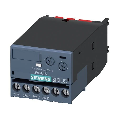
| product brand name | SIRIUS |
| Article Number | 3RA2815-1FW10 |
| product designation | Solid-state time-delay auxiliary switch |
| product type designation | 3RA28 |
| General technical data | |
| size of contactor can be combined company-specific | S00, S0, S2, S3 |
| product component semi-conductor output | No |
| product extension required remote control | No |
| product extension optional remote control | No |
| insulation voltage for overvoltage category III according to | 300 V |
| IEC 60664 with degree of pollution 3 rated value | |
| test voltage for isolation test | 1.5 kV |
| degree of pollution | 3 |
| surge voltage resistance rated value | 4 kV |
| test voltage for surge voltage test | 4 800 V |
| protection class IP of the terminal | IP20 |
| shock resistance according to IEC 60068-2-27 | 15g / 11 ms |
| vibration resistance according to IEC 60068-2-6 | 10 … 59 Hz: 0.35 mm, 60 … 150 Hz: 2g |
| mechanical service life (switching cycles) typical | 10 000 000 |
| mechanical service life (switching cycles) | |
| ● with contactor 3R.2 of frame size S00 | 10 000 000 |
| ● with contactor 3R.2 of frame size S0 | 10 000 000 |
| ● with contactor 3R.2 of frame size S2 | 10 000 000 |
| ● with contactor 3R.2 of frame size S3 | 10 000 000 |
| electrical endurance (switching cycles) at AC-15 at 230 V typical | 100 000 |
| electrical endurance (switching cycles) | |
| ● with contactor 3R.2 of frame size S00 | 100 000 |
| ● with contactor 3R.2 of frame size S0 | 100 000 |
| ● with contactor 3R.2 of frame size S2 | 100 000 |
| ● with contactor 3R.2 of frame size S3 | 100 000 |
| adjustable time | 0.05 … 100 s |
| relative setting accuracy relating to full-scale value | 15% |
| minimum ON period | 200 ms |
| recovery time | 150 ms |
| reference code according to IEC 81346-2 | K |
| relative repeat accuracy | 1% |
| influence of the surrounding temperature | ±1 % |
| power supply influence | ±1 % |
| Substance Prohibitance (Date) | 10/1/2009 |
| Product Function | |
| product function star-delta circuit | No |
| Control circuit/ Control | |
| type of voltage of the control supply voltage | AC/DC |
| control supply voltage 1 at AC | |
| ● at 50 Hz | 24 … 240 V |
| ● at 60 Hz | 24 … 240 V |
| control supply voltage frequency 1 | 50 … 60 Hz |
| control supply voltage 1 | |
| ● at DC | 24 … 240 V |
| operating range factor control supply voltage rated | |
| value at DC | |
| ● initial value | 0.85 |
| ● full-scale value | 1.1 |
| operating range factor control supply voltage rated | |
| value at AC at 50 Hz | |
| ● initial value | 0.85 |
| ● full-scale value | 1.1 |
| operating range factor control supply voltage rated | |
| value at AC at 60 Hz | |
| ● initial value | 0.85 |
| ● full-scale value | 1.1 |
| design of the surge suppressor with | with varistor |
| Switching Function | |
| switching function | |
| ● ON-delay | No |
| ● ON-delay/instantaneous contact | No |
| ● passing make contact | No |
| ● passing make contact/instantaneous contact | No |
| ● OFF delay | Yes |
| switching function | |
| ● flashing symmetrically with interval start/instantaneous | No |
| ● flashing symmetrically with interval start | No |
| ● flashing symmetrically with pulse start/instantaneous | No |
| ● flashing symmetrically with pulse start | No |
| ● flashing asymmetrically with interval start | No |
| ● flashing asymmetrically with pulse start switching function | No |
| switching function | |
| ● constant clock cycle with pulse start | No |
| ● constant clock cycle with interval start switching function | No |
| switching function | |
| ● variably clocked with pulse start | No |
| ● variably clocked with interval start switching function | No |
| switching function | |
| ● star-delta circuit with delay time | No |
| ● star-delta circuit | No |
| switching function with control signal | |
| ● additive ON-delay | No |
| ● passing break contact | No |
| ● passing break contact/instantaneous | No |
| ● OFF delay | No |
| ● OFF delay/instantaneous | No |
| ● pulse delayed | No |
| ● pulse delayed/instantaneous | No |
| ● pulse-shaping | No |
| ● pulse-shaping/instantaneous | No |
| ● additive ON-delay/instantaneous | No |
| ● ON-delay/OFF-delay | No |
| ● ON-delay/OFF-delay/instantaneous | No |
| ● passing make contact | No |
| ● passing make contact/instantaneous contact | No |
| switching function of interval relay with control signal | |
| ● retrotriggerable with deactivated control signal/instantaneous contact | No |
| ● retrotriggerable with switched-on control signal | No |
| ● retrotriggerable with switched-on control | No |
| signal/instantaneous contact | |
| ● retriggerable with deactivated control signal | No |
| design of the control terminal non-floating | No |
| Short-circuit protection | |
| design of the fuse link for short-circuit protection of the auxiliary switch required | fuse gL/gG: 4 A |
| Auxiliary circuit | |
| material of switching contacts | AgNi |
| number of NC contacts | |
| ● delayed switching | 1 |
| number of NO contacts | |
| ● delayed switching | 1 |
| operational current of auxiliary contacts at AC-15 | |
| ● maximum | 3 A |
| ● at 24 V | 3 A |
| ● at 250 V | 3 A |
| operational current of auxiliary contacts as NC contact at AC-15 | |
| ● at 24 V | 3 A |
| ● at 250 V | 3 A |
| operational current of auxiliary contacts as NO contact at AC-15 | |
| ● at 24 V | 3 A |
| ● at 250 V | 3 A |
| operational current of auxiliary contacts at DC-13 | 1 … 0.1 |
| operational current of auxiliary contacts at DC-13 | |
| ● at 24 V | 1 A |
| ● at 125 V | 0.2 A |
| ● at 250 V | 0.1 A |
| operating frequency with 3RT2 contactor maximum | 2 500 1/h |
| contact rating of auxiliary contacts according to UL | B300 / R300 |
| Main circuit | |
| type of voltage | AC/DC |
| Inputs/ Outputs | |
| product function | |
| ● at the relay outputs switchover delayed/without | No |
| ● non-volatile | No |
| Electromagnetic compatibility | |
| EMC immunity according to IEC 61812-1 | Environment A (industrial area) |
| conducted interference | |
| ● due to burst according to IEC 61000-4-4 | 2 kV network connection / 1 kV control connection |
| ● due to conductor-earth surge according to IEC 61000-4-5 | 2 kV |
| ● due to conductor-conductor surge according to IEC 61000-4-5 | 1 kV |
| field-based interference according to IEC 61000-4-3 | 10 V/m |
| electrostatic discharge according to IEC 61000-4-2 | 8 kV |
| Safety related data | |
| protection class IP on the front according to IEC 60529 | IP20 |
| type of insulation | Basic insulation |
| category according to EN 954-1 | none |
| Connections/ Terminals | |
| product component removable terminal for auxiliary | Yes |
| and control circuit | |
| type of electrical connection for auxiliary and control circuit | screw-type terminals |
| type of connectable conductor cross-sections | |
| ● solid | 0.5 … 4 mm², 2x (0.5 … 2.5 mm²) |
| ● finely stranded with core end processing | 1x (0.5 … 2.5 mm²), 2x (0.5 … 1.5 mm²) |
| ● at AWG cables solid | 2x (20 … 14) |
| ● at AWG cables stranded | 2x (20 … 14) |
| connectable conductor cross-section | |
| ● solid | 0.5 … 4 mm² |
| ● finely stranded with core end processing | 0.5 … 2.5 mm² |
| ● finely stranded without core end processing | 0.25 … 1.5 mm² |
| AWG number as coded connectable conductor cross | |
| section | |
| ● solid | 20 … 14 |
| ● stranded | 20 … 14 |
| Installation/ mounting/ dimensions | |
| mounting position | any (like contactor) |
| fastening method | clip-on |
| height | 38 mm |
| width | 45 mm |
| depth | 74 mm |
| required spacing | |
| ● with side-by-side mounting | |
| — forwards | 0 mm |
| — backwards | 0 mm |
| — upwards | 0 mm |
| — downwards | 0 mm |
| — at the side | 0 mm |
| ● for grounded parts | |
| — forwards | 0 mm |
| — backwards | 0 mm |
| — upwards | 0 mm |
| — at the side | 0 mm |
| — downwards | 0 mm |
| ● for live parts | |
| — forwards | 0 mm |
| — backwards | 0 mm |
| — upwards | 0 mm |
| — downwards | 0 mm |
| — at the side | 0 mm |
| Ambient conditions | |
| installation altitude at height above sea level maximum | 2 000 m |
| ambient temperature | |
| ● during operation | -25 … +60 °C |
| ● during storage | -40 … +85 °C |
| ● during transport | -40 … +85 °C |
| relative humidity during operation | 0 … 95 % |