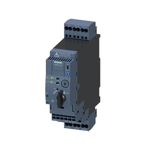
| product brand name | SIRIUS |
| product designation | compact starter |
| design of the product | direct starter |
| product type designation | 3RA61 |
| General technical data | |
| product function control circuit interface to parallel wiring | Yes |
| product extension auxiliary switch | Yes |
| power loss [W] for rated value of the current ● at AC in hot operating state ● at AC in hot operating state per pole ● without load current share typical |
0.18 W 0.6 W 2.9 W |
| insulation voltage rated value | 690 V |
| degree of pollution | 3 |
| surge voltage resistance rated value | 6 000 V |
| maximum permissible voltage for protective separation ● between main and auxiliary circuit ● between auxiliary and auxiliary circuit ● between control and auxiliary circuit |
400 V 250 V 300 V |
| degree of protection NEMA rating | other |
| shock resistance | a=60 m/s2 (6g) with 10 ms per 3 shocks in all axes |
| vibration resistance | f= 4 … 5.8 Hz, d= 15 mm; f= 5.8 … 500 Hz, a= 20 m/s²; 10 cycles |
| mechanical service life (operating cycles) ● of the main contacts typical ● of auxiliary contacts typical ● of the signaling contacts typical |
10 000 000 10 000 000 10 000 000 |
| electrical endurance (operating cycles) of auxiliary contacts ● at DC-13 at 6 A at 24 V typical ● at AC-15 at 6 A at 230 V typical |
30 000 200 000 |
| type of assignment | continous operation according to IEC 60947-6-2 |
| reference code according to IEC 81346-2 | Q |
| Substance Prohibitance (Date) | 5/1/2012 |
| SVHC substance name | Lead – 7439-92-1 Lead monoxide (lead oxide) – 1317-36-8 2,2′,6,6′-tetrabromo-4,4′-isopropylidenediphenol – 79-94-7 6,6′-di-tert-butyl-2,2′-methylenedi-p-cresol – 119-47-1 Lead titanium zirconium oxide – 12626-81-2 |
| Weight | 1.565 kg |
| Ambient conditions | |
| installation altitude at height above sea level maximum | 2 000m |
| ambient temperature ● during operation ● during storage ● during transport |
-20 … +60 °C -55 … +80 °C -55 … +80 °C |
| relative humidity during operation | 10 … 90 % |
| Main circuit | |
| number of poles for main current circuit | 3 |
| adjustable current response value current of the current dependent overload release |
3..12A |
| formula for making capacity limit current | 12 x le |
| formula for limit current breaking capacity | 10 x le |
| yielded mechanical performance for 4-pole AC motor ● at 400 V rated value ● at 500 V rated value ● at 690 V rated value |
5.5kW 5.5kW 7.5kW |
| operating voltage at AC-3 rated value maximum | 690 V |
| operational current ● at AC at 400 V rated value ● at AC-3 at 400 V rated value ● at AC-43 — at 400 V rated value — at 500 V rated value — at 690 V rated value |
12A 12A11.5A 12.4A 8.9A |
| operating power ● at AC-3 at 400 V rated value ● at AC-43 — at 400 V rated value — at 500 V rated value — at 690 V rated value |
5.5kW5 500 W 5 500 W 7 500 W |
| no-load switching frequency | 3 600 1/h |
| operating frequency ● at AC-41 according to IEC 60947-6-2 maximum ● at AC-43 according to IEC 60947-6-2 maximum |
750 1/h 250 1/h |
| Control circuit/ Control | |
| type of voltage | AC/DC |
| control supply voltage 1 at AC ● at 50 Hz rated value ● at 50 Hz ● at 60 Hz rated value ● at 60 Hz |
24 V 24…24V 24V 24V |
| control supply voltage frequency ● 1 rated value ● 2 rated value |
50 Hz 60 Hz |
| control supply voltage 1 at DC rated value | 24 V |
| control supply voltage 1 at DC | 24…24V |
| holding power ● at AC maximum ● at DC maximum |
2.8W 2.9W |
| Auxiliary circuit | |
| number of NC contacts for auxiliary contacts | 1 |
| number of NO contacts for auxiliary contacts | 1 |
| number of NO contacts of instantaneous short-circuit trip unit for signaling contact |
1 |
| number of CO contacts of the current-dependent overload release for signaling contact |
1 |
| operational current of auxiliary contacts at AC-12 maximum | 10 A |
| operational current of auxiliary contacts at DC-13 at 250 V | 0.27 A |
| Protective and monitoring functions | |
| trip class | CLASS 10 and 20 adjustable |
| operating short-circuit current breaking capacity (Ics) ● at 400 V rated value ● at 500 V rated value ● at 690 V rated value |
53 kA 3 kA 3 KA |
| UL/CSA ratings | |
| full-load current (FLA) for 3-phase AC motor ● at 480 V rated value ● at 600 V rated value |
12A 12A |
| yielded mechanical performance [hp] for 3-phase AC motor ● at 200/208 V rated value ● at 220/230 V rated value ● at 460/480 V rated value ● at 575/600 V rated value |
3 hp 3 hp 7.5 hp 10 hp |
| contact rating of auxiliary contacts according to UL | contacts 21-22, 13-14, 43-44 Q600 / A600, contacts 77-78 R300 / B300, contacts 95-96-98 R300 / D300 |
| Short-circuit protection | |
| product function short circuit protection | Yes |
| design of short-circuit protection | electromagnetic |
| design of the fuse link ● for short-circuit protection of the auxiliary switch required ● for short-circuit protection of the signaling switch of the short-circuit release required ● for short-circuit protection of the signaling switch of the overload release required |
fuse gL/gG: 10 A 6A gL/gG/400V4A gL/gG/400V |
| Installation/ mounting/ dimensions | |
| mounting position | any |
| mounting position recommended | vertical, on horizontal standard DIN rail |
| fastening method | screw and snap-on mounting |
| height | 191mm |
| width | 45mm |
| depth | 165mm |
| Connections/ Terminals | |
| product component removable terminal for main circuit | Yes |
| product component removable terminal for auxiliary and control circuit |
Yes |
| type of electrical connection ● for main current circuit ● for auxiliary and control circuit |
spring-loaded terminals spring-loaded terminals |
| type of connectable conductor cross-sections for main contacts ● solid ● finely stranded with core end processing ● finely stranded without core end processing |
2x (1.5 … 6 mm²), 1x 10 mm² 2x (1.5 … 6 mm²) 2x (1.5 … 6 mm²) |
| type of connectable conductor cross-sections ● for auxiliary contacts — solid — finely stranded with core end processing — finely stranded without core end processing ● for AWG cables for auxiliary contacts |
2x (0.25 … 1.5 mm²) 2x (0.25 … 1.5 mm²) 2x (0.25 … 1.5 mm²) 2x (24 … 16) |
| Safety related data | |
| proportion of dangerous failures ● with low demand rate according to SN 31920 ● with high demand rate according to SN 31920 |
40 % 50 % |
| B10 value with high demand rate according to SN 31920 | 3 000 000 |
| failure rate [FIT] with low demand rate according to SN 31920 |
100 FIT |
| IEC 61508 | |
| T1 value for proof test interval or service life according to IEC 61508 |
20 a |
| Electrical Safety | |
| protection class IP on the front according to IEC 60529 | IP20 |
| touch protection on the front according to IEC 60529 | finger-safe |
| Communication/ Protocol | |
| product function bus communication | |
| protocol is supported ● AS-Interface protocol ● IO-Link protocol |
No No |
| product function control circuit interface with IO link | No |
| Electromagnetic compatibility | |
| conducted interference ● due to burst according to IEC 61000-4-4 ● due to conductor-earth surge according to IEC 61000-4-5 ● due to conductor-conductor surge according to IEC 61000-4-5 ● due to high-frequency radiation according to IEC 61000 4-6 |
4 kV main contacts, 2 kV auxiliary contacts 4 kV main contacts, 2 kV auxiliary contacts 2 kV main contacts, 1 kV auxiliary contacts0.15-80Mhz at 10V |
| field-based interference according to IEC 61000-4-3 | 10 V/m |
| electrostatic discharge according to IEC 61000-4-2 | 8 kV |
| conducted HF interference emissions according to CISPR11 |
150 kHz … 30 MHz Class A |
| field-bound HF interference emission according to CISPR11 | 30 … 1000 MHz Class A |
| Supply voltage | |
| Supply voltage required Auxiliary voltage | No |
| Display | |
| number of LEDs | 2 |