Part Number: 1073211
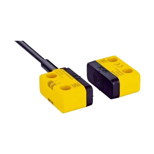
Safety switches: STR1-SASF0AC5
| System part | Sensor with actuator |
| Sensor principle | RFID |
| Number of safe outputs | 2 |
| Auxiliary contact (AUX) | 1 (Switching behavior complementary to OSSDs) |
| Safe switch on distance Sao | 10 mm (–30 °C … +70 °C) 1) |
| Safe switch off distance Sar | 25 mm 1) |
| Active sensor surfaces | 3 |
| Active sensor surface | Top, sides (left, right) 2) |
| Actuation directions | 5 |
| Coding | Permanently coded |
1) Values apply for the frontal alignment of the sensor to the actuator. A detailed display of the alignment options and values can be found in the operating instructions.
2) For details see operating instructions.
| Safety integrity level | SIL 3 (IEC 61508) |
| Category | Category 4 (EN ISO 13849) |
| Performance level | PL e (EN ISO 13849) |
| PFHD (mean probability of a dangerous failure per hour) | 5,21 x 10⁻⁹ |
| TM (mission time) | 20 years (EN ISO 13849) |
| Type | Type 4 (EN ISO 14119) |
| Actuator coding level | High coding level (EN ISO 14119) |
| Safe state in the event of a fault | At least one safety-related semiconductor output (OSSD) is in the OFF state. |
| Safe series connections | With Flexi Loop (with diagnostics) |
|
|||||||||||||||||||||
|
|||||||||||||||||||||
| Protection class | III (IEC 61140) |
| Classification according to cULus | Class 2 |
| Supply voltage Vs | 24 V DC (19.2 V DC … 28.8 V DC) |
| Power consumption | 50 mA |
| Type of output | Self-monitoring semiconductor outputs (OSSDs) |
| Output current | ≤ 100 mA |
| Response time | 40 ms 1) |
| Release time | 100 ms 1) 2) |
| Risk time | 80 ms 1) 3) |
| Switch-on time | 2.5 s 4) |
1) In a safe series connection, each downstream safety switch increases the system response time. More response times can be found in the operating instructions.
2) Response time on approach to the enable zone.
3) Detection time for internal oder external faults (e.g., short-circuit or cross-circuit of output signal switching devices). Follow the detailed information in the operating instructions.
4) The time specified applies to one sensor after the supply voltage has been applied to the safety switch. In a safe series connection, 0.1¬s must be added for each sensor. An additional 0.5¬s per taught-in actuator must be added for uniquely coded and permanently coded sensors.
| Dimensions (W x H x D) | 40 mm x 18 mm x 26 mm |
| Weight | 82 g |
| Housing material | VISTAL® |
| Enclosure rating | IP67, IP69K (EN 60529, ISO 20653) |
| Ambient operating temperature | –30 °C … +70 °C 1) |
| Storage temperature | –30 °C … +70 °C |
| Vibration resistance | 10 Hz … 55 Hz, 1 mm (IEC 60068-2-6) |
| Shock resistance | 30 g, 11 ms (IEC 60068-2-27) |
| EMC | EN IEC 61326-3-1
EN IEC 60947-5-2 EN IEC 60947-5-3 EN 300330 V2.1.1 |
1) Only applies for safety switches whose serial numbers begin with number series 1825**** or higher. For safety switches whose serial numbers deviate from this, an ambient operating temperature of-10 °C … +70 °C applies.
The serial number is displayed on the safety switch over the data matrix code.