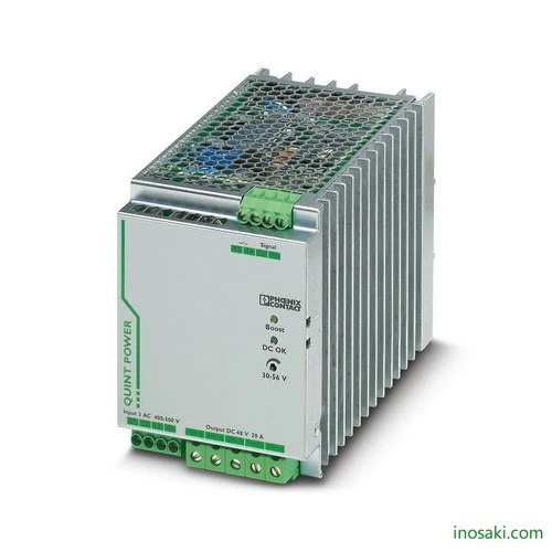
Reliable Phoenix Contact QUINT-PS/3AC/48DC/20 power supply, 48 V DC 20 A, with SFB and POWER BOOST for maximum uptime in industrial automation.
The Phoenix Contact QUINT-PS/3AC/48DC/20 power supply is engineered to provide dependable 48 V DC at 20 A for critical industrial applications. Built for demanding environments, it incorporates advanced features like Selective Fuse Breaking (SFB) and a strong power reserve to guarantee uninterrupted performance. Its adjustable output voltage, high efficiency, and three-phase compatibility make it a robust solution for automation panels and control systems that require both flexibility and reliability. Preventive monitoring functions further enhance system safety by identifying potential issues before they impact operations.
Designed for maximum uptime, the QUINT-PS/3AC/48DC/20 combines power reserves with intelligent diagnostics to support heavy start-up loads and reduce costly downtime. The static POWER BOOST ensures consistent delivery of extra current when needed, while SFB technology rapidly trips standard circuit breakers to protect connected devices. Its compact DIN rail format and wide adjustment range enable seamless integration into diverse setups, from factory machinery to process control environments. By combining rugged construction, high efficiency, and early fault detection, this unit delivers long-term operational stability and reduced maintenance costs.
The QUINT-PS/3AC/48DC/20 is built for industries where failure is not an option. It combines robust 3-phase input, intelligent monitoring, and high efficiency into one compact unit. With adjustable voltage, strong overload capability, and selective circuit breaker tripping, it provides the kind of rock-solid reliability that keeps automation and control systems running without interruption.
This power supply tackles the critical challenge of unexpected downtime in industrial systems. By ensuring stable power during heavy load start-ups and quickly isolating faulty circuits, it prevents system-wide shutdowns. Its preventive monitoring adds another layer of security, alerting operators before failures occur—making it a smart safeguard for productivity and safety in modern operations.
| Feature | Details | Benefit |
|---|---|---|
| Input Voltage Range | 3-phase 400–500 V AC / 500–600 V DC | Flexible integration into diverse industrial power systems |
| Output Voltage | 48 V DC (adjustable 30–56 V DC) | Allows precise tuning for varied load requirements |
| Output Current | 20 A nominal, up to 22.5 A with POWER BOOST | Reliable support for heavy start-up loads |
| SFB Technology | Delivers 6× nominal current for 12 ms | Ensures fast circuit breaker tripping, preventing downtime |
| Efficiency | Up to 93% | Reduces energy loss and operational costs |
| Preventive Monitoring | Detects critical operating states in advance | Early warning prevents failures and costly stoppages |
| Mounting | DIN rail, screw connection | Easy installation and maintenance in control cabinets |
| Dimensions (W x H x D) | 96 × 130 × 179 mm | Compact design saves space in panels |
| Protection Class | IP20 | Safe and suitable for industrial environments |
| Operating Temperature | –25 °C to +70 °C (with derating above 60 °C) | Reliable in harsh conditions and wide environments |
| Standards & Approvals | UL 508, IEC/EN 61010, CSA, CE | Certified for global industrial compliance |
| Parallel/Series Connection | Supported | Expand capacity or create redundancy |
Download Phoenix Contact QUINT-PS/3AC/48DC/20 (2320827) Datasheet
| Commercial Attribute | Details |
|---|---|
| GTIN (EAN Number) | 4046356547734 |
| Tariff Number (HS Code) | 85044095 |
| Weight (Net) | 2,500 g |
| Weight (Including Packaging) | 2,912.1 g |
| Country of Origin | Thailand (TH) |
Large conveyor systems in manufacturing often face sudden load demands when motors start. The QUINT-PS/3AC/48DC/20 addresses this with its POWER BOOST capability, providing extra current to ensure motors start smoothly without tripping the supply. Its SFB technology rapidly isolates faulty circuits, preventing widespread shutdowns across the production line. With early warning diagnostics, maintenance teams gain valuable insight into potential issues, reducing unplanned stoppages and protecting overall equipment efficiency.
Automated warehouse robots need stable power when docking at charging stations. This power supply offers adjustable voltage and high efficiency, ensuring reliable charging while minimizing energy waste. The permanent power reserve delivers the surge needed when multiple robots simultaneously connect or disconnect, avoiding downtime in busy operations. Preventive monitoring functions provide early alerts if voltage levels drift, helping facility managers maintain seamless autonomous workflows and ensuring uninterrupted logistics performance.
Wind farms and solar plants require dependable power for their control and monitoring cabinets. The QUINT-PS/3AC/48DC/20 accepts both AC and DC inputs, making it suitable for fluctuating renewable energy conditions. Its rapid breaker-tripping ability protects sensitive controllers from faults during load surges, while the extra current reserve guarantees stable startup of auxiliary equipment. Built for harsh environments, it maintains efficiency and provides advance diagnostic alerts, helping operators avoid costly interruptions and ensuring consistent energy generation.
In safety-critical building systems, emergency lighting must activate immediately during power failures. The QUINT-PS/3AC/48DC/20 supplies steady 48 V DC output and uses its power reserve to support sudden load activation when lights switch on. Its selective circuit protection ensures one faulty line doesn’t compromise the entire emergency network. With compact DIN-rail installation and continuous health monitoring, building managers can depend on this supply to keep evacuation routes illuminated and comply with strict safety regulations.
| Category | Model | Article Number | Description | Benefit |
|---|---|---|---|---|
| Mounting Accessories | UTA 107 | 2853983 | Universal DIN rail adapter for secure mounting | Ensures stable installation in control cabinets |
| UWA 182/52 | 2938235 | Wall adapter for secure fastening under vibration | Reliable mounting in harsh or mobile environments | |
| Redundancy Module | QUINT-DIODE/48DC/2X20/1X40 | 2320160 | Diode module for redundancy, 2×20 A or 1×40 A | Guarantees continuous supply in redundant systems |
| TRIO-DIODE/48DC/2X10/1X20 | 2866527 | Redundancy module with function monitoring | Improves system safety and load balancing | |
| Circuit Breaker | CB TM1 1A SFB P | 2800836 | 1-pole breaker, SFB tripping characteristic, 1 A | Fast isolation of faulty circuits |
| CB TM1 2A SFB P | 2800837 | 1-pole breaker, SFB tripping characteristic, 2 A | Protects sensitive low-current devices | |
| CB TM1 3A SFB P | 2800838 | 1-pole breaker, SFB tripping characteristic, 3 A | Optimized for selective fuse breaking | |
| CB TM1 4A SFB P | 2800839 | 1-pole breaker, SFB tripping characteristic, 4 A | Prevents wider system interruptions | |
| CB TM1 5A SFB P | 2800840 | 1-pole breaker, SFB tripping characteristic, 5 A | Effective branch protection for mid-range loads | |
| CB TM1 6A SFB P | 2800841 | 1-pole breaker, SFB tripping characteristic, 6 A | Reliable downstream protection | |
| CB TM1 8A SFB P | 2800842 | 1-pole breaker, SFB tripping characteristic, 8 A | Suitable for heavier load applications | |
| CB TM1 10A SFB P | 2800843 | 1-pole breaker, SFB tripping characteristic, 10 A | High-load protection with rapid fault isolation | |
| Surge Protection | PLT-SEC-T3-3S-230-FM | 2905230 | Type 3 surge protector for 3-phase networks | Shields system against voltage spikes |
| PLT-SEC-T3-60-FM-UT | 2907917 | Type 3 surge protection for AC/DC networks, 60 V | Compact device safeguarding sensitive circuits |
For expert guidance before placing your order.
Warranty – 1-year warranty for your peace of mind.
Global Shipping – We ship worldwide with secure packaging and reliable delivery.
Technical Support – Contact us for professional after-sales technical assistance.