Phoenix Contact develops terminal blocks, distribution blocks, power supplies, relays, connectors, signal conditioners, controllers & PLCs, I/O systems, Industrial Ethernet, controller system cabling, PCB terminal blocks & connectors, and surge suppression.
| Item number | 3273310 |
| Packing unit | 8 pc |
| Minimum order quantity | 8 pc |
| Product key | BEA115 |
| Catalog page | Page 439 (C-1-2019) |
| GTIN | 4055626392226 |
| Weight per piece (including packing) | 32.625 g |
| Weight per piece (excluding packing) | 32.625 g |
| Customs tariff number | 85369010 |
| Country of origin | PL |
| Notes on operation | the blocks can be bridged with one another via the conductor shaft, for corresponding plug-in bridges, see accessories |
| General | |
| Note | The maximum load current of a single clamping unit must not be exceeded. |
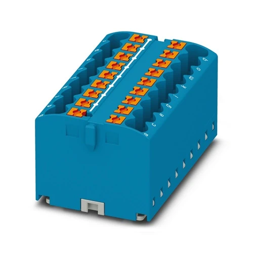
| Product type | Distributor terminal block |
| Number of connections | 18 |
| Number of rows | 1 |
| Potentials | 1 |
| Insulation characteristics | |
| Overvoltage category | III |
| Degree of pollution | 3 |
| Rated surge voltage | 6 kV |
| Maximum power dissipation for nominal condition | 0.77 W |
Connection Data
| Number of connections per level | 18 |
| Nominal cross section | 2.5 mm² |
| Rated cross section AWG | 12 |
| Stripping length | 8 mm … 10 mm |
| Internal cylindrical gage | A3 |
| Connection in acc. with standard | IEC 60998-2-2 |
| Conductor cross section rigid | 0.14 mm² … 4 mm² |
| Cross section AWG | 26 … 12 (converted acc. to IEC) |
| Conductor cross section flexible | 0.14 mm² … 4 mm² |
| Conductor cross section, flexible [AWG] | 26 … 12 (converted acc. to IEC) |
| Conductor cross-section flexible (ferrule without plastic sleeve) | 0.14 mm² … 2.5 mm² |
| Flexible conductor cross section (ferrule with plastic sleeve) | 0.14 mm² … 2.5 mm² |
| Nominal current | 24 A |
| Maximum load current | 32 A |
| Maximum total current | 48 A |
| Nominal voltage | 450 V |
| Connection cross sections directly pluggable | |
| Conductor cross section rigid | 0.34 mm² … 4 mm² |
| Conductor cross section, rigid [AWG] | 24 … 12 (converted acc. to IEC) |
| Conductor cross-section flexible (ferrule without plastic sleeve) | 0.34 mm² … 2.5 mm² |
| Flexible conductor cross section (ferrule with plastic sleeve) | 0.34 mm² … 2.5 mm² |
| Width | 46.9 mm |
| Height | 28.6 mm |
| Depth | 21.7 mm |
| Color | blue (RAL 5015) |
| Flammability rating according to UL 94 | V0 |
| Insulating material group | I |
| Insulating material | PA |
| Static insulating material application in cold | -60 °C |
| Temperature index of insulation material (DIN EN 60216-1 (VDE 0304-21)) | 130 °C |
| Relative insulation material temperature index (Elec., UL 746 B) | 130 °C |
| Fire protection for rail vehicles (DIN EN 45545-2) R22 | HL 1 – HL 3 |
| Fire protection for rail vehicles (DIN EN 45545-2) R23 | HL 1 – HL 3 |
| Fire protection for rail vehicles (DIN EN 45545-2) R24 | HL 1 – HL 3 |
| Fire protection for rail vehicles (DIN EN 45545-2) R26 | HL 1 – HL 3 |
| Calorimetric heat release NFPA 130 (ASTM E 1354) | 28 MJ/kg |
| Surface flammability NFPA 130 (ASTM E 162) | passed |
| Specific optical density of smoke NFPA 130 (ASTM E 662) | passed |
| Smoke gas toxicity NFPA 130 (SMP 800C) | passed |
| Mechanical data | |
| Open side panel | No |
| Attachment on the carrier | |
| Result | Test passed |
| Note | When aligning several blocks, it is recommended to either place a DIN rail adapter underneath the connection point or a flange element between the blocks. |
| For versions with 6 or 7 connections, it is enough to place one DIN rail adapter centrally per block and place flange elements after every other block. | |
| When using the DIN rail adapter PTFIX-NS35, an aligned block must not protrude by more than a half. | |
| Needle-flame test | |
| Time of exposure | 30 s |
| Result | Test passed |
| Oscillation/broadband noise | |
| Specification | DIN EN 50155 (VDE 0115-200):2008-03 |
| Spectrum | Long life test category 2, bogie-mounted |
| Frequency | f1 = 5 Hz to f2 = 250 Hz |
| ASD level | 6.12 (m/s²)²/Hz |
| Acceleration | 3.12g |
| Test duration per axis | 5 h |
| Test directions | X-, Y- and Z-axis |
| Result | Test passed |
| Shocks | |
| Specification | DIN EN 50155 (VDE 0115-200):2008-03 |
| Pulse shape | Half-sine |
| Acceleration | 30g |
| Shock duration | 18 ms |
| Number of shocks per direction | 3 |
| Test directions | X-, Y- and Z-axis (pos. and neg.) |
| Result | Test passed |
| Ambient conditions | |
| Ambient temperature (operation) | -60 °C … 110 °C (Operating temperature range incl. self-heating; for max. short-term operating temperature, see RTI Elec.) |
| Ambient temperature (storage/transport) | -25 °C … 60 °C (for a short time, not exceeding 24 h, -60 °C to +70 °C) |
| Ambient temperature (assembly) | -5 °C … 70 °C |
| Ambient temperature (actuation) | -5 °C … 70 °C |
| Permissible humidity (operation) | 20 % … 90 % |
| Permissible humidity (storage/transport) | 30 % … 70 % |
| Connection in acc. with standard | IEC 60998-2-2 |
| Mounting type | for snapping onto a DIN rail adapter |
| Direct mounting with flange | |
| Free-hanging |