Phoenix Contact develops terminal blocks, power supplies, relays, connectors, signal conditioners, controllers & PLCs, I/O systems, Industrial Ethernet, controller system cabling, PCB terminal blocks & connectors, and surge suppression.
| Item number | 2902037 |
| Packing unit | 1 pc |
| Minimum order quantity | 1 pc |
| Product key | DK1121 |
| Catalog page | Page 72 (C-5-2019) |
| GTIN | 4046356649728 |
| Weight per piece (including packing) | 121.7 g |
| Weight per piece (excluding packing) | 103.9 g |
| Customs tariff number | 85437090 |
| Country of origin | DE |
| Utilization restriction | |
| EMC note | EMC: class A product, see manufacturer’s declaration in the download area |
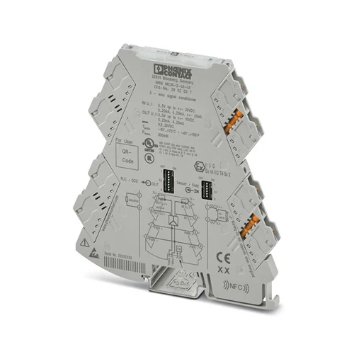
| Product type | Signal conditioner |
| Product family | MINI Analog Pro |
| No. of channels | 1 |
| Type | Signal conditioner |
| Configuration | DIP switches |
| Insulation characteristics: GB Standard | |
| Overvoltage category | II |
| Pollution degree | 2 |
| Electrical isolation | 3-way isolation |
| Electrical isolation between input and output | yes |
| Limit frequency (3 dB) | 30 Hz (via DIP switch) |
| 5 kHz (via DIP switch) | |
| Protective circuit | Transient protection |
| Step response (10-90%) | < 12 ms (with 30 Hz filter) |
| Maximum temperature coefficient | 0.01 %/K |
| Temperature coefficient, typical | 0.01 %/K |
| Maximum transmission error | ≤ 0.1 % (of the maximum value of the configured output range) |
| ≤ 0.15 % (of final value, at IN: 4 mA … 20 mA / OUT: -10 V … 10 V) | |
| Electrical isolation Input/output/power supply | |
| Rated insulation voltage | 300 Vrms |
| Test voltage | 3 kV AC (50 Hz, 60 s) |
| Insulation | Reinforced insulation according to IEC/EN 61010-1 |
| Supply | |
| Nominal supply voltage | 24 V DC |
| Supply voltage range | 9.6 V DC … 30 V DC (The DIN rail connector (ME 6,2 TBUS-2 1,5/5-ST-3,81 GN, item no. 2869728) can be used to bridge the supply voltage. It can be snapped onto a 35 mm DIN rail in accordance with EN 60715) |
| Typical current consumption | 25 mA (Current output, at 24 V DC incl. load) |
| 54 mA (Current output, at 12 V DC incl. load) | |
| Power consumption | ≤ 800 mW (at IOUT = 20 mA, 9.6 V DC, 600 Ω load) |
| Signal: Voltage/current | |
| Number of inputs | 1 |
| Configurable/programmable | Yes |
| Voltage input signal | 0 V … 5 V (via DIP switch) |
| 1 V … 5 V (via DIP switch) | |
| -5 V … 5 V (via DIP switch) | |
| 0 V … 10 V (via DIP switch) | |
| 2 V … 10 V (via DIP switch) | |
| -10 V … 10 V (via DIP switch) | |
| 0 V … 20 V (via DIP switch) | |
| 4 V … 20 V (via DIP switch) | |
| -20 V … 20 V (via DIP switch) | |
| 0 V … 24 V (via DIP switch) | |
| 4.8 V … 24 V (via DIP switch) | |
| -24 V … 24 V (via DIP switch) | |
| 0 V … 30 V (via DIP switch) | |
| 6 V … 30 V (via DIP switch) | |
| -30 V … 30 V (via DIP switch) | |
| Max. voltage input signal | 33 V |
| Current input signal | 0 mA … 20 mA (via DIP switch) |
| 4 mA … 20 mA (via DIP switch) | |
| -20 mA … 20 mA (via DIP switch) | |
| Max. current input signal | 24 mA |
| Input resistance of voltage input | > 1000 kΩ |
| Input resistance current input | approx. 63 Ω (+0.7 V for test diode) |
| Signal: Voltage/current | |
| Number of outputs | 1 |
| Configurable/programmable | Yes |
| Voltage output signal | 0 V … 5 V (via DIP switch) |
| 1 V … 5 V (via DIP switch) | |
| -5 V … 5 V (via DIP switch) | |
| 0 V … 10 V (via DIP switch) | |
| 2 V … 10 V (via DIP switch) | |
| -10 V … 10 V (via DIP switch) | |
| Non-load voltage | < 17 V |
| Current output signal | 0 mA … 20 mA (via DIP switch) |
| 4 mA … 20 mA (via DIP switch) | |
| Max. current output signal | 22 mA |
| Short-circuit current | < 32 mA |
| Load/output load voltage output | ≥ 10 kΩ |
| Load/output load current output | ≤ 600 Ω (at 20 mA) |
| Ripple | < 20 mVPP (at 600 Ω) |
| < 20 mVPP (at 600 Ω) | |
| Connection method | Screw connection |
| Stripping length | 10 mm |
| Screw thread | M3 |
| Conductor cross section rigid | 0.2 mm² … 1.5 mm² (with ferrule) |
| 0.14 mm² … 2.5 mm² (without ferrule) | |
| Conductor cross section flexible | 0.14 mm² … 2.5 mm² |
| Conductor cross section AWG | 24 … 12 (flexible) |
| Tightening torque | 0.5 Nm … 0.6 Nm |
| Ex installation (EPL) | Gc |
| Div. 2 |
| Status display | Green LED (supply voltage) |
| Width | 6.2 mm |
| Height | 109.81 mm |
| Depth | 119.2 mm |
| Color | gray (RAL 7042) |
| Housing material | PBT |
| Fire protection for rail vehicles (DIN EN 45545-2) R22 | HL 1 – HL 2 |
| Fire protection for rail vehicles (DIN EN 45545-2) R23 | HL 1 – HL 2 |
| Fire protection for rail vehicles (DIN EN 45545-2) R24 | HL 1 – HL 2 |
| Ambient conditions | |
| Degree of protection | IP20 (not assessed by UL) |
| Ambient temperature (operation) | -40 °C … 70 °C |
| Ambient temperature (storage/transport) | -40 °C … 85 °C |
| Altitude | ≤ 2000 m |
| Permissible humidity (operation) | 5 % … 95 % (non-condensing) |
| CE | |
| Certificate | CE-compliant |
| ATEX | |
| Identification | II 3 G Ex ec ic IIC T4 Gc |
| Certificate | BVS 19 ATEX E 047 X |
| IECEx | |
| Identification | Ex ec ic IIC T4 Gc |
| Certificate | IECEx BVS 19.0041X |
| CCC / China-Ex | |
| Identification | Ex ec ic IIC T4 Gc |
| Certificate | 2022122310115961 |
| UL, USA/Canada | |
| Identification | UL 508 Listed |
| Class I, Div. 2, Groups A, B, C, D T6 | |
| Class I, Zone 2, Group IIC T6 | |
| Shipbuilding approval | |
| Certificate | DNV GL TAA00002UA |
| EAC Ex | |
| Identification | 2Ex ec ic IIC T4 Gc |
| Certificate | BY/112 02.01 TP012 103.01 00079 |
| Shipbuilding data | |
| Temperature | B |
| Humidity | B |
| Vibration | A |
| EMC | A |
| Enclosure | Required protection according to the Rules shall be provided upon installation on board |
| Electromagnetic compatibility | Conformance with EMC directive |
| Noise immunity | EN 61000-6-2 |
| Note | When being exposed to interference, there may be minimal deviations. |
| Noise emission | |
| Standards/regulations | EN 61000-6-4 |
| Electrostatic discharge | |
| Standards/regulations | EN 61000-4-2 |
| Electrostatic discharge | |
| Comments | Safety measures must be taken to prevent electrostatic discharge. |
| Electromagnetic HF field | |
| Designation | Electromagnetic RF field |
| Standards/regulations | EN 61000-4-3 |
| Fast transients (burst) | |
| Designation | Fast transients (burst) |
| Standards/regulations | EN 61000-4-4 |
| Surge current load (surge) | |
| Standards/regulations | EN 61000-4-5 |
| Conducted interference | |
| Designation | Conducted interferences |
| Standards/regulations | EN 61000-4-6 |
| Mounting type | DIN rail mounting |
| Assembly note | The DIN rail connector can be used for bridging the supply voltage. It can be snapped onto a 35 mm EN 60715 DIN rail. |
| Mounting position | any |