Phoenix Contact develops terminal blocks, power supplies, relays, connectors, signal conditioners, controllers & PLCs, I/O systems, Industrial Ethernet, controller system cabling, PCB terminal blocks & connectors, and surge suppression.
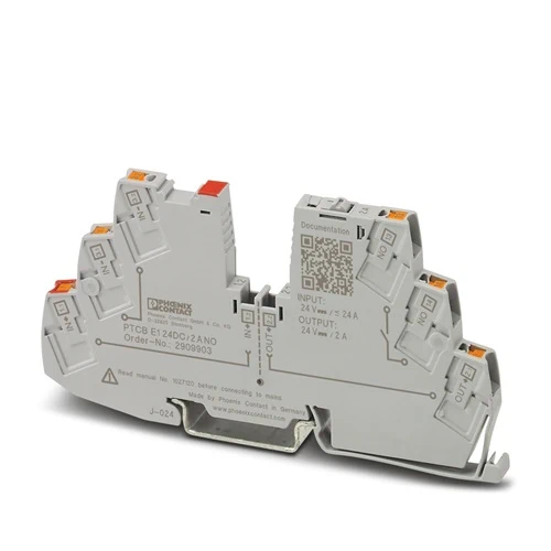
| Item number | 2909903 |
| Packing unit | 1 pc |
| Minimum order quantity | 1 pc |
| Product key | CLA135 |
| Catalog page | Page 378 (C-4-2019) |
| GTIN | 4055626408712 |
| Weight per piece (including packing) | 34.7 g |
| Weight per piece (excluding packing) | 27.58 g |
| Customs tariff number | 85363010 |
| Country of origin | DE |
| General | |
| Note | EN 50121-3-2: Railway applications – Electromagnetic compatibility – Part 3-2: Rolling stock – Apparatus |
| Connection for signal line tested in accordance with EN 61000-4-4 with 1 kV; if necessary, customer must provide appropriate protective measures | |
| Repeated hard short circuits can reduce the melting integral of the integrated backup fuse. | |
| Product type | Device circuit breakers |
| Product family | PTCB |
| Type | DIN rail module, one-piece |
| Number of positions | 1 |
| No. of channels | 1 |
| Insulation characteristics | |
| Protection class | III |
| Pollution degree | 2 |
| General | |
| Operating voltage | 18 V DC … 30 V DC |
| Rated voltage | 24 V DC |
| Rated current IN | 24 A DC (Total current input) |
| 2 A DC (Rated current output) | |
| Rated current (pre-adjusted) | 2 A |
| Rated surge voltage | 0.5 kV |
| Tripping method | E (electronic) |
| Feedback resistance | max. 35 V DC |
| Required backup fuse | Only required if Imax of the power supply > the short-circuit switching capacity. Integrated failsafe element. |
| Short-circuit switching capacity | 300 A |
| Dielectric strength | max. 35 V DC (Load circuit) |
| Fuse | electronic |
| Efficiency | > 99 % |
| Closed circuit current I0 | typ. 12 mA |
| Power dissipation | typ. 0.3 W (No-load operation) |
| < 0.8 W (Nominal operation) | |
| Module initialization time | < 0.55 s |
| Waiting time after switch off of a channel | 5 s (at overload / short circuit) |
| Measuring tolerance I | ± 15 % |
| Temperature derating | 21 A (Total current at 60°C) |
| 24 A (Total current at 50°C) | |
| 2 A (Channel current at 60°C) | |
| 2 A (Channel current at 50°C) | |
| MTBF (IEC 61709, SN 29500) | 28571428 h (at 25 °C with 21 % load) |
| 14084507 h (at 40°C with 34.25% load) | |
| 2053388 h (at 60°C with 100% load) | |
| Voltage drop | 0.06 V (at 2 A) |
| Fail-safe element | 4 A DC |
| Contact switching type | without electrical isolation |
| Load circuit | |
| Shutdown time | ≤ 10 ms (for short circuit > 2.0 x IN) |
| 1 s (1.2 … 2.0 x IN) | |
| Undervoltage switch-off | ≤ 17.8 V DC (active) |
| ≥ 18.8 V DC (inactive) | |
| Overvoltage switch-off | ≥ 30.5 V DC (active) |
| ≤ 29.5 V DC (inactive) | |
| Max. capacitive load | 14000 µF (Depending on the available short-circuit current) |
| Indicator/remote signaling | |
| Connection name | Remote indication circuit |
| Switching function | N/O contact |
| Operating voltage | 0 V DC … 30 V DC |
| Operating current | 100 mA DC |
| Main circuit IN+ | |
| Connection method | Push-in connection |
| Stripping length | 8 mm |
| Conductor cross section flexible | 0.2 mm² … 2.5 mm² |
| Conductor cross section rigid | 0.2 mm² … 4 mm² |
| Conductor cross section AWG | 24 … 12 |
| Conductor cross section, flexible, with ferrule, with plastic sleeve | 0.2 mm² … 2.5 mm² |
| Conductor cross section flexible, with ferrule without plastic sleeve | 0.2 mm² … 2.5 mm² |
| Main circuit IN- | |
| Connection method | Push-in connection |
| Stripping length | 8 mm |
| Conductor cross section flexible | 0.2 mm² … 2.5 mm² |
| Conductor cross section rigid | 0.2 mm² … 4 mm² |
| Conductor cross section AWG | 24 … 12 |
| Conductor cross section, flexible, with ferrule, with plastic sleeve | 0.2 mm² … 2.5 mm² |
| Conductor cross section flexible, with ferrule without plastic sleeve | 0.2 mm² … 2.5 mm² |
| Main circuit OUT | |
| Connection method | Push-in connection |
| Stripping length | 8 mm |
| Conductor cross section flexible | 0.2 mm² … 2.5 mm² |
| Conductor cross section rigid | 0.2 mm² … 4 mm² |
| Conductor cross section AWG | 24 … 12 |
| Conductor cross section, flexible, with ferrule, with plastic sleeve | 0.2 mm² … 2.5 mm² |
| Conductor cross section flexible, with ferrule without plastic sleeve | 0.2 mm² … 2.5 mm² |
| Remote indication circuit | |
| Connection method | Push-in connection |
| Stripping length | 10 mm |
| Conductor cross section flexible | 0.2 mm² … 2.5 mm² |
| Conductor cross section rigid | 0.2 mm² … 4 mm² |
| Conductor cross section AWG | 24 … 14 |
| Conductor cross section, flexible, with ferrule, with plastic sleeve | 0.2 mm² … 2.5 mm² |
| Conductor cross section flexible, with ferrule without plastic sleeve | 0.2 mm² … 2.5 mm² |
| Channel LED off | off (Channel switched off) |
| Channel LED yellow | lit (Channel switched on, channel load > 80% ) |
| flashing (Programming mode active) | |
| Channel LED green | lit (Channel switched on) |
| Channel LED red | lit (Channel switched off, over- or undervoltage active) |
| ON temporarily (Channel switched off, 5 s cool-down phase, overload or short-circuit release) | |
| flashing (Channel switched off, ready to be switched back on, overload or short-circuit release) | |
| flashing quickly (Channel switched off, external voltage at the output, possible installation error) |
| Width | 6.2 mm |
| Height | 105.8 mm |
| Depth | 55.6 mm (incl. DIN rail 7.5 mm) |
| Color | gray (RAL 7042) |
| Material | PBT |
| PBT | |
| Flammability rating according to UL 94 | V-0 |
| Ambient conditions | |
| Degree of protection | IP20 |
| Ambient temperature (operation) | -30 °C … 60 °C |
| Ambient temperature (storage/transport) | -40 °C … 70 °C |
| Altitude | ≤ 3000 m up to 52 °C (amsl) |
| ≤ 4000 m up to 46 °C (amsl) | |
| Humidity test | 96 h, 95 % RH, 40 °C |
| Shock (operation) | 30g (IEC 60068-2-27, Test Ea) |
| Vibration (operation) | 10 Hz … 59.6 Hz (Amplitude ±0.35 mm; in accordance with IEC 60068-2-6, Test Fc) |
| 59.6 Hz … 150 Hz (Acceleration 5g; in accordance with IEC 60068-2-6, Test Fc) | |
| 5 Hz … 100 Hz (Resonance search 4g; resonance frequency 4g; 90 min in accordance with DNV GL Class B) | |
| UL approval | |
| Identification | UL/C-UL Listed UL 508 |
| UL Recognized UL 2367 | |
| NEC Class 2 according to UL 1310 | |
| UL/C-UL Listed ANSI/UL 121201 Class I, Division 2, Groups A, B, C, D; T4 (Hazardous Location) | |
| Shipbuilding approval | |
| Identification | DNV GL |
| Corrosive gas test | |
| Identification | ISA S71.04.2013 G3 Harsh Group A |
| Shipbuilding data | |
| Temperature | D |
| Humidity | B |
| Vibration | B |
| EMC | B |
| Enclosure | A |
| Standards/specifications | EN 61000-6-2 |
| Note | EMC – Immunity for industrial areas |
| Standards/specifications | EN 61000-6-3 |
| Note | EMC – Emission for residential, business and commercial properties and small operations |
| Standards/specifications | EN 60068-2-78 |
| Note | Environmental influences – Moisture and heat, constant |
| Standards/specifications | EN 50178 |
| Note | Equipping power installations with electronic equipment |
| Standards/specifications | EN 60068-2-6 |
| Note | Environmental influences – Vibrations (sinusoidal) |
| Standards/specifications | EN 60068-2-27 |
| Note | Environmental influences – Shocks |
| Standards/specifications | EN 60068-2-30 |
| Note | Environmental influences – Part 2–30: Tests – Test Db: Damp heat, cyclical |
| Standards/specifications | EN 61373 |
| Note | Railway applications – Rolling stock equipment – Shock and vibration tests |
| Standards/specifications | EN 45545-2 |
| Note | Railway applications – Fire protection on railway vehicles – Part 2: Requirements for fire behavior of materials and components |
Mounting
| Mounting type | DIN rail: 35 mm |