| Note |
Notes on operation the blocks can be bridged with one another via the conductor shaft, for corresponding plug-in bridges, see accessories |
| Part Number |
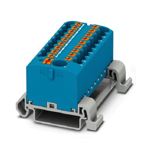
3273244 |
| Number of rows |
1 |
| Number of connections |
19 |
| Potentials |
1 |
| Nominal cross section |
2.5 mm² |
| Color |
blue |
| Insulating material |
PA |
| Flammability rating according to UL 94 |
V0 |
| Mounting type |
NS 35/7,5 |
| Rated surge voltage |
8 kV |
| Degree of pollution |
3 |
| Overvoltage category |
III |
| Insulating material group |
I |
| Maximum power dissipation for nominal condition |
0.77 W |
| Maximum load current |
32 A (with 4 mm² conductor cross section) |
| Maximum total current |
57 A (with 10 mm² conductor cross section) |
| Nominal current IN |
24 A |
| Nominal voltage UN |
690 V |
| Maximum load current |
57 A (with 10 mm² conductor cross section) |
| Nominal current IN |
41 A (with 6 mm² conductor cross section) |
| Open side panel |
No |
| General information |
The maximum load current of a single clamping unit must not be exceeded. For power distribution applications, IEC 60364-4-43.2008; modified + corrigendum Okt. 2008 (DIN VDE 0100-430:2010-10) section 433.2 ff must be observed! |
| Shock protection test specification |
DIN EN 50274 (VDE 0660-514):2002-11 |
| Back of the hand protection |
guaranteed |
| Finger protection |
guaranteed |
| Result of surge voltage test |
Test passed |
| Result of power-frequency withstand voltage test |
Test passed |
| Power frequency withstand voltage setpoint |
1.89 kV |
| Result of the test for mechanical stability of terminal points (5 x conductor connection) |
Test passed |
| Result of flexion and pull-out test |
Test passed |
| Bending test rotation speed |
10 rpm |
| Bending test turns |
135 |
| Bending test conductor cross section/weight |
0.5 mm² / 0.3 kg |
|
6 mm² / 1.4 kg |
|
10 mm² / 2 kg |
|
0.14 mm² / 0.2 kg |
|
2.5 mm² / 0.7 kg |
|
4 mm² / 0.9 kg |
| Tensile test result |
Test passed |
| Conductor cross section tensile test |
0.5 mm² |
| Tractive force setpoint |
20 N |
| Conductor cross section tensile test |
6 mm² |
| Tractive force setpoint |
80 N |
| Conductor cross section tensile test |
10 mm² |
| Tractive force setpoint |
90 N |
| Conductor cross section tensile test |
0.14 mm² |
| Tractive force setpoint |
10 N |
| Result of tight fit on support |
Test passed |
| Tight fit on carrier |
NS 35 |
| Setpoint |
5 N |
| Note |
When aligning several blocks, it is recommended to either place a DIN rail adapter underneath the connection point or a flange element between the blocks. |
|
For versions with 6 or 7 connections, it is enough to place one DIN rail adapter centrally per block and place flange elements after every other block. |
|
When using the DIN rail adapter PTFIX-NS35, an aligned block must not protrude by more than a half. |
| Result of voltage-drop test |
Test passed |
| Requirements, voltage drop |
U1 ≤ 3.2 mV; U2 ≤ 1.5 x U1 |
| Result of temperature-rise test |
Test passed |
| Requirement temperature-rise test |
Increase in temperature ≤ 45 K |
| Short circuit stability result |
Test passed |
| Conductor cross section short circuit testing |
6 mm² |
| Short-time current |
0.72 kA |
| Conductor cross section short circuit testing |
10 mm² |
| Short-time current |
1.2 kA |
| Result of thermal test |
Test passed |
| Proof of thermal characteristics (needle flame) effective duration |
30 s |
| Result of aging test |
Test passed |
| Ageing test for screwless modular terminal block temperature cycles |
192 |
| Oscillation, broadband noise test result |
Test passed |
| Test specification, oscillation, broadband noise |
DIN EN 50155 (VDE 0115-200):2008-03 |
| Test spectrum |
Service life test category 2, bogie-mounted |
| Test frequency |
f1 = 5 Hz to f2 = 250 Hz |
| ASD level |
6.12 (m/s²)²/Hz |
| Acceleration |
3.12g |
| Test duration per axis |
5 h |
| Test directions |
X-, Y- and Z-axis |
| Shock test result |
Test passed |
| Test specification, shock test |
DIN EN 50155 (VDE 0115-200):2008-03 |
| Shock form |
Half-sine |
| Acceleration |
30g |
| Shock duration |
18 ms |
| Number of shocks per direction |
3 |
| Test directions |
X-, Y- and Z-axis (pos. and neg.) |
| Relative insulation material temperature index (Elec., UL 746 B) |
130 °C |
| Temperature index of insulation material (DIN EN 60216-1 (VDE 0304-21)) |
130 °C |
| Static insulating material application in cold |
-60 °C |
| Surface flammability NFPA 130 (ASTM E 162) |
passed |
| Specific optical density of smoke NFPA 130 (ASTM E 662) |
passed |
| Calorimetric heat release NFPA 130 (ASTM E 1354) |
28 MJ/kg |
| Smoke gas toxicity NFPA 130 (SMP 800C) |
passed |
| Fire protection for rail vehicles (DIN EN 45545-2) R22 |
HL 1 – HL 3 |
| Fire protection for rail vehicles (DIN EN 45545-2) R23 |
HL 1 – HL 3 |
| Fire protection for rail vehicles (DIN EN 45545-2) R24 |
HL 1 – HL 3 |
| Fire protection for rail vehicles (DIN EN 45545-2) R26 |
HL 1 – HL 3 |