Phoenix Contact develops terminal blocks, power supplies, relays, connectors, signal conditioners, controllers & PLCs, I/O systems, Industrial Ethernet, controller system cabling, PCB terminal blocks & connectors, and surge suppression.
| Item number | 2320186 |
| Packing unit | 1 pc |
| Minimum order quantity | 1 pc |
| Product key | CMRQ43 |
| Catalog page | Page 303 (C-4-2019) |
| GTIN | 4046356524919 |
| Weight per piece (including packing) | 764.9 g |
| Weight per piece (excluding packing) | 557 g |
| Customs tariff number | 85371091 |
| Country of origin | IN |
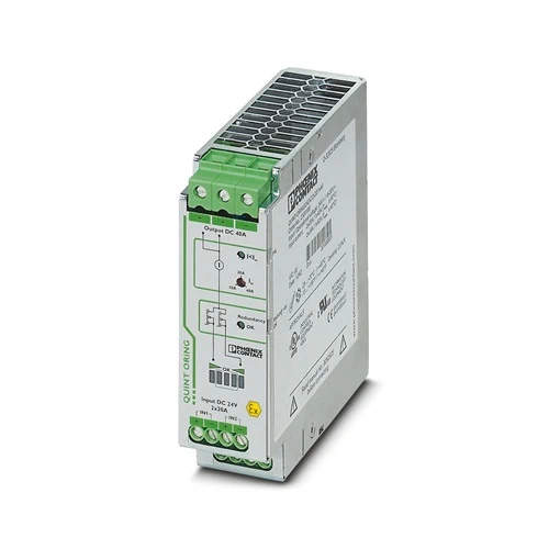
| Product type | Redundancy module |
| Product family | QUINT ORING |
| MTBF (IEC 61709, SN 29500) | > 720000 h (40 °C) |
| LED | yes |
| Insulation characteristics | |
| Protection class | III |
| Degree of pollution | 2 |
| Insulation voltage input, output / housing | 500 V |
| DC operation | |
| Nominal input voltage range | 24 V DC |
| Input voltage range | 18 V DC … 28 V DC (SELV) |
| Input voltage range DC | 18 V DC … 28 V DC (SELV) |
| Voltage type of supply voltage | DC |
| Reverse polarity protection | < yes60 V |
| Nominal input current (IN) | 2x 20 A (-25 °C … 60 °C) |
| 1x 40 A (-25 °C … 60 °C) | |
| Maximum current Imax | 2x 26 A (-25 °C … 40 °C) |
| 1x 52 A (-25 °C … 40 °C) | |
| 120 A (12 ms, SFB Technology) | |
| Transient surge protection | Varistor |
| Voltage drop, input/output | 0.2 V (IOUT = 40 A) |
| Efficiency | > 98 % |
| Nominal output voltage | UIn – 0,2 V |
| Nominal output current (IN) | 40 A (Increasing power) |
| 20 A (Redundancy) | |
| Derating | 60 °C … 70 °C (2.5 %/K) |
| Protection against overvoltage at the output (OVP) | < 32 V DC |
| Power loss nominal load max. | 8 W (IOUT = 40 A) |
| Connection in series | no |
| Signal: Redundancy OK, 13/14 | |
| Output description | Group contact |
| Maximum switching voltage | max. 30 V AC/DC |
| Maximum inrush current | ≤ 100 mA (short-circuit-proof) |
| Signal: ACB (Auto Current Balancing) OK, 23/24 | |
| Output description | Contact closed: Δ UIN ≤ 300 mV |
| Maximum switching voltage | max. 30 V AC/DC |
| Maximum inrush current | ≤ 100 mA (short-circuit-proof) |
| Input | |
| Connection method | Screw connection |
| Conductor cross section, rigid min. | 0.2 mm² |
| Conductor cross section, rigid max. | 6 mm² |
| Conductor cross section flexible min. | 0.2 mm² |
| Conductor cross section flexible max. | 4 mm² |
| Conductor cross section AWG min. | 10 |
| Stripping length | 8 mm |
| Screw thread | M3 |
| Tightening torque, min | 0.5 Nm |
| Tightening torque max | 0.6 Nm |
| Output | |
| Connection method | Screw connection |
| Conductor cross section, rigid min. | 0.5 mm² |
| Conductor cross section, rigid max. | 16 mm² |
| Conductor cross section flexible min. | 0.5 mm² |
| Conductor cross section flexible max. | 16 mm² |
| Conductor cross section AWG min. | 6 |
| Stripping length | 10 mm |
| Screw thread | M4 |
| Tightening torque, min | 1.2 Nm |
| Tightening torque max | 1.5 Nm |
| Signal | |
| Connection method | Screw connection |
| Conductor cross section, rigid min. | 0.2 mm² |
| Conductor cross section, rigid max. | 6 mm² |
| Conductor cross section flexible min. | 0.2 mm² |
| Conductor cross section flexible max. | 4 mm² |
| Conductor cross section AWG min. | 16 |
| Conductor cross section AWG max. | 10 |
| Stripping length | 10 mm |
| Screw thread | M3 |
| Tightening torque, min | 0.5 Nm |
| Tightening torque max | 0.6 Nm |
| Types of signaling | Relay contact, floating, current limited |
| Signal output: Redundancy OK, 13/14 | |
| Status display | LED redundancy OK |
| Note on status display | green |
| Color | green |
| Signal output: ACB (Auto Current Balancing) OK, 23/24 | |
| Status display | ACB OK LED |
| Note on status display | LED bar graph green |
| Color | green |
| Note on status display | LED bar graph green |
| Width | 38 mm |
| Height | 130 mm |
| Depth | 125 mm |
| Horizontal pitch | 2.1 Div. |
| Installation dimensions | |
| Installation distance right/left | 5 mm / 5 mm |
| Installation distance top/bottom | 50 mm / 50 mm |
| Alternative assembly | |
| Width | 122 mm |
| Height | 130 mm |
| Depth | 41 mm |
| Flammability rating according to UL 94 (housing / terminal blocks) | V0 |
| Housing material | Metal |
| Type of housing | Aluminum (AlMg3) |
| Hood version | Galvanized sheet steel, free from chrome (VI) |
| Ambient conditions | |
| Degree of protection | IP20 |
| Ambient temperature (operation) | -25 °C … 70 °C (> 60 °C Derating: 2,5 %/K) |
| Ambient temperature (storage/transport) | -40 °C … 85 °C |
| Maximum altitude | 2000 m |
| Climatic class | 3K3 (in acc. with EN 60721) |
| Max. permissible relative humidity (operation) | ≤ 100 % (at 25 °C, non-condensing) |
| Shock | 18 ms, 30g, in each space direction (according to IEC 60068-2-27) |
| Vibration (operation) | < 15 Hz, amplitude ±2.5 mm (according to IEC 60068-2-6) |
| 15 Hz … 150 Hz, 2.3g, 90 min. | |
| Temp code | T4 (-25 … +70 °C; > 60 °C, Derating: 2,5 %/K) |
| Standard – Electronic equipment for use in electrical power installations and their assembly into electrical power installations | EN 50178/VDE 0160 (PELV) |
| Standard – Electrical safety | EN 60950-1/VDE 0805 (SELV) |
| Standard – Safety extra-low voltage | IEC 60950-1 (SELV) and EN 60204-1 (PELV) |
| Noxious gas test | ISA-S71.04-1985 G3 Harsh Group A |
| UL approvals | UL/C-UL listed UL 508 |
| UL/C-UL Recognized UL 60950-1 | |
| UL ANSI/ISA-12.12.01 Class I, Division 2, Groups A, B, C, D T3C … T4 (Hazardous Location) | |
| Conformity/Approvals | |
| ATEX | II 3 G Ex ec nC IIC T4 Gc |
| DEKRA 20ATEX0136 X | |
| IECEx | Ex ec nC IIC T4 Gc |
| DEK 20.0082X | |
| Electromagnetic compatibility | Conformance with EMC Directive 2014/30/EU |
| Low Voltage Directive | Conformance with Low Voltage Directive 2014/35/EC |
| EMC requirements for noise emission | EN 61000-6-3 |
| EN 61000-6-4 | |
| EMC requirements for noise immunity | EN 61000-6-1 |
| EN 61000-6-2 | |
| Electrostatic discharge | |
| Standards/regulations | EN 61000-4-2 |
| Electrostatic discharge | |
| Contact discharge | 8 kV (Test Level 4) |
| Discharge in air | 15 kV (Test Level 4) |
| Comments | Criterion B |
| Electromagnetic HF field | |
| Standards/regulations | EN 61000-4-3 |
| Electromagnetic HF field | |
| Frequency range | 80 MHz … 1 GHz |
| Test field strength | 20 V/m (Test Level 3) |
| Frequency range | 1 GHz … 2 GHz |
| Test field strength | 10 V/m (Test Level 3) |
| Frequency range | 2 GHz … 3 GHz |
| Test field strength | 10 V/m (Test Level 3) |
| Comments | Criterion A |
| Fast transients (burst) | |
| Standards/regulations | EN 61000-4-4 |
| Fast transients (burst) | |
| Input | 2 kV (Test Level 3 – asymmetrical) |
| Output | 2 kV (Test Level 3 – asymmetrical) |
| Signal | 2 kV (Test Level 4 – asymmetrical) |
| Comments | Criterion B |
| Surge voltage load (surge) | |
| Standards/regulations | EN 61000-4-5 |
| Surge voltage load (surge) | |
| Input | 0.5 kV (Test Level 1 – symmetrical) |
| 0.5 kV (Test Level 1 – asymmetrical) | |
| Output | 0.5 kV (Test Level 1 – symmetrical) |
| 0.5 kV (Test Level 1 – asymmetrical) | |
| Signal | 1 kV (Test Level 2 – asymmetrical) |
| Comments | Criterion B |
| Conducted interference | |
| Standards/regulations | EN 61000-4-6 |
| Conducted interference | |
| Input/output/signal | asymmetrical |
| Frequency range | 0.15 MHz … 80 MHz |
| Comments | Criterion A |
| Voltage | 10 V (Test Level 3) |
| Emitted interference | |
| Standards/regulations | EN 61000-6-3 |
| Radio interference voltage in acc. with EN 55011 | EN 55011 (EN 55022) Class B, area of application: Industry and residential |
| Emitted radio interference in acc. with EN 55011 | EN 55011 (EN 55022) Class B, area of application: Industry and residential |
| Criteria | |
| Criterion A | Normal operating behavior within the specified limits. |
| Criterion B | Temporary impairment to operational behavior that is corrected by the device itself. |
| Mounting type | DIN rail mounting |
| Assembly note | alignable: PN ≥50%, 5 mm horizontally, 15 mm next to active components, 50 mm vertically alignable: PN <50%, 0 mm horizontally, 40 mm vertically top, 20 mm vertically bottom |
| Mounting position | horizontal DIN rail NS 35, EN 60715 |