Inosaki – Your Trusted Phoenix Contact Distributor
Inosaki proudly stands as one of the largest distributors of Phoenix Contact products, offering a comprehensive range of terminal blocks, interface modules, power supplies, and relays.
Series Models: PT Series, ST Series, TB Series, UT Series, and UK Series, PTV Series, UKH Series, Micro Series.
Discover industry-leading Phoenix Contact power supplies, such as:
Get Your Phoenix Contact Catalog Today
Need detailed product information? Contact us at sales@inosaki.com to request your Phoenix Contact catalog.
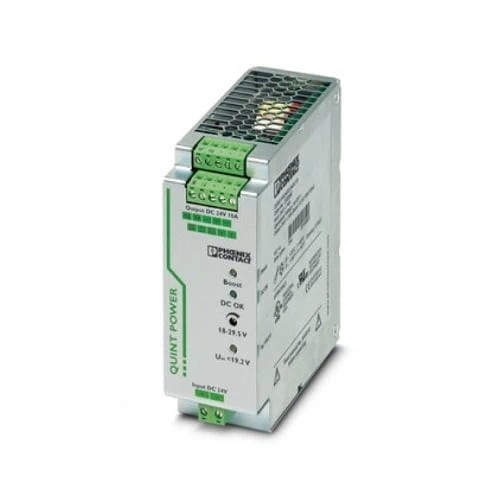
QUINT DC/DC converter with maximum functionality
DC/DC converters alter the voltage level, regenerate the voltage at the end of long cables or enable the creation of independent supply systems by means of electrical isolation.
QUINT DC/DC converters magnetically and therefore quickly trip circuit breakers with six times the nominal current, for selective and therefore cost-effective system protection. The high level of system availability is additionally ensured, thanks to preventive function monitoring, as it reports critical operating states before errors occur.
| Width | 48 mm |
| Height | 130 mm |
| Depth | 125 mm |
| Installation dimensions | |
| Installation distance right/left | 0 mm / 0 mm (≤ 70 °C) |
| Installation distance right/left (active) | 15 mm / 15 mm (≤ 70 °C) |
| Installation distance top/bottom | 50 mm / 50 mm (≤ 70 °C) |
| Installation distance top/bottom (active) | 50 mm / 50 mm (≤ 70 °C) |
| Width | 122 mm |
| Height | 130 mm |
| Depth | 51 mm |
| Degree of protection | IP20 |
| Ambient temperature (operation) | -25 °C … 70 °C (> 60 °C derating, 2.5 %/K, startup at -40°C type-tested) |
| Ambient temperature (storage/transport) | -40 °C … 85 °C |
| Ambient temperature (start-up type tested) | -40 °C |
| Climatic class | 3K3 (in acc. with EN 60721) |
| Max. permissible relative humidity (operation) | ≤ 95 % (at 25 °C, non-condensing) |
| Shock | 18 ms, 30g, in each space direction (according to IEC 60068-2-27) |
| Vibration (operation) | < 5 Hz, amplitude ±1.6 mm (according to IEC 60068-2-6) |
| 5 Hz … 100 Hz, 4g, 90 min. |
| Nominal input voltage range | 24 V DC |
| Input voltage range | 18 V DC … 32 V DC |
| Extended input voltage range in operation | 14 V DC … 18 V DC (Derating) |
| Wide-range input | no |
| Input voltage range DC | 18 V DC … 32 V DC |
| 14 V DC … 18 V DC (Consider derating during operation) | |
| Voltage type of supply voltage | DC |
| Inrush current | < 15 A (typical) |
| Inrush current integral (I2t) | < 2.7 A2s |
| Mains buffering time | > 12 ms (24 V DC) |
| Current consumption | 14 A (24 V, IBOOST) |
| Reverse polarity protection | ≤ 30 V DC |
| Protective circuit | Transient surge protection; Varistor |
| Input fuse | 25 A (internal (device protection)) |
| Recommended breaker for input protection | 16 A … 20 A (Characteristics B, C, D, K) |
| Efficiency | > 92 % |
| Output characteristic | U/I |
| Nominal output voltage | 24 V DC ±1 % |
| Setting range of the output voltage (USet) | 18 V DC … 29.5 V DC (> 24 V DC, constant capacity restricted) |
| Nominal output current (IN) | 10 A (-25 °C … 60 °C) |
| POWER BOOST (IBoost) | 12.5 A (-25 °C … 40 °C permanent, UOUT = 24 V DC ) |
| Selective Fuse Breaking (ISFB) | 60 A (12 ms) |
| Magnetic circuit breaker tripping | B2 / B4 / B6 / C2 / C4 |
| Derating | 60 °C … 70 °C (2.5%/K) |
| Feedback voltage resistance | 35 V DC |
| Protection against overvoltage at the output (OVP) | < 35 V DC |
| Max. capacitive load | unlimited |
| Active current limitation | Approx. 18 A |
| Control deviation | < 1 % (change in load, static 10 % … 90 %) |
| < 2 % (change in load, dynamic 10 % … 90 %) | |
| < 0.1 % (change in input voltage ±10 %) | |
| Residual ripple | < 20 mVPP |
| Output power | 240 W |
| Peak switching voltages nominal load | < 10 mVPP (20 MHz) |
| Maximum no-load power dissipation | 1.6 W |
| Power loss nominal load max. | 24 W |
| Rise time | < 2 ms (UOUT (10 % … 90 %)) |
| Connection in parallel | yes, for redundancy and increased capacity |
| Connection in series | yes |
| 2 (Devices) |
Signal: DC OK active
| Output description | UOUT > 0.9 x UN: High signal |
| Switching voltage range | 18 V DC … 24 V DC |
| Maximum inrush current | < 20 mA (short-circuit-proof) |
Signal: POWER BOOST, active
| Output description | IOUT < IN: High signal |
| Switching voltage range | 18 V DC … 24 V DC |
| Maximum inrush current | < 20 mA (short-circuit-proof) |
Signal: UIN OK, active
| Output description | UIN > 19.2 V: High signal |
| Switching voltage range | 18 V DC … 24 V DC |
| Maximum inrush current | ≤ 20 mA (short-circuit-proof) |
Signal: DC OK floating
| Output description | Relay |
| Output voltage | ≤ 30 V AC/DC |
| Maximum inrush current | ≤ 100 mA |
| Item number | 2320092 |
| Packing unit | 1 pc |
| Minimum order quantity | 1 pc |
| Sales Key | CM05 |
| Product Key | CMDQ43 |
| Catalog Page | Page 248 (C-4-2017) |
| GTIN | 4046356481885 |
| Weight per Piece (including packing) | 1,162.5 g |
| Weight per Piece (excluding packing) | 900 g |
| Customs tariff number | 85044083 |
| Country of origin | IN |
| Connection method | Pluggable screw connection |
| Conductor cross section, rigid min. | 0.2 mm² |
| Conductor cross section, rigid max. | 2.5 mm² |
| Conductor cross section flexible min. | 0.2 mm² |
| Conductor cross section flexible max. | 2.5 mm² |
| Conductor cross section AWG min. | 24 |
| Conductor cross section AWG max. | 12 |
| Stripping length | 8 mm |
| Screw thread | M3 |
| Tightening torque, min | 0.5 Nm |
| Tightening torque max | 0.6 Nm |
| Connection method | Pluggable screw connection |
| Conductor cross section, rigid min. | 0.2 mm² |
| Conductor cross section, rigid max. | 2.5 mm² |
| Conductor cross section flexible min. | 0.2 mm² |
| Conductor cross section flexible max. | 2.5 mm² |
| Conductor cross section AWG min. | 24 |
| Conductor cross section AWG max. | 12 |
| Stripping length | 7 mm |
| Screw thread | M3 |
| Tightening torque, min | 0.5 Nm |
| Tightening torque max | 0.6 Nm |
| Conductor cross section, rigid min. | 0.2 mm² |
| Conductor cross section, rigid max. | 2.5 mm² |
| Conductor cross section flexible min. | 0.2 mm² |
| Conductor cross section flexible max. | 2.5 mm² |
| Conductor cross section AWG min. | 24 |
| Conductor cross section AWG max. | 12 |
| Screw thread | M3 |
| Tightening torque, min | 0.5 Nm |
| Tightening torque max | 0.6 Nm |
| Rail applications | EN 50121-4 |
| Standard – Electronic equipment for use in electrical power installations and their assembly into electrical power installations | EN 50178/VDE 0160 (PELV) |
| Standard – Electrical safety | EN 60950-1/VDE 0805 (SELV) |
| Standard – Safety extra-low voltage | EN 60950-1 (SELV) |
| EN 60204 (PELV) | |
| Standard – Safe isolation | DIN VDE 0100-410 |
| Shipbuilding approval | DNV GL (EMC B) |
| UL approvals | UL/C-UL listed UL 508 |
| UL/C-UL Recognized UL 60950-1 | |
| UL ANSI/ISA-12.12.01 Class I, Division 2, Groups A, B, C, D (Hazardous Location) |
| EMC requirements for noise emission | EN 61000-6-3 |
| EN 61000-6-4 | |
| EMC requirements for noise immunity | EN 61000-6-1 |
| EN 61000-6-2 | |
| Electromagnetic compatibility | Conformance with EMC Directive 2014/30/EU |
| Electrostatic discharge | |
| Standards/regulations | EN 61000-4-2 |
| Electrostatic discharge | |
| Contact discharge | 8 kV (Test Level 4) |
| Discharge in air | 15 kV (Test Level 4) |
| Comments | Criterion A |
| Electromagnetic HF field | |
| Standards/regulations | EN 61000-4-3 |
| Electromagnetic HF field | |
| Frequency range | 80 MHz … 1 GHz |
| Test field strength | 10 V/m (Test Level 3) |
| Frequency range | 1 GHz … 2 GHz |
| Test field strength | 10 V/m (Test Level 3) |
| Frequency range | 2 GHz … 3 GHz |
| Test field strength | 10 V/m (Test Level 3) |
| Comments | Criterion A |
| Fast transients (burst) | |
| Standards/regulations | EN 61000-4-4 |
| Fast transients (burst) | |
| Input | 2 kV (Test Level 3 – asymmetrical) |
| Output | 2 kV (Test Level 3 – asymmetrical) |
| Signal | 2 kV (Test Level 4 – asymmetrical) |
| Comments | Criterion A |
| Surge voltage load (surge) | |
| Standards/regulations | EN 61000-4-5 |
| Input | 1 kV (Test Level 2 – symmetrical) |
| 2 kV (Test Level 3 – asymmetrical) | |
| Output | 1 kV (Test Level 2 – symmetrical) |
| 2 kV (Test Level 3 – asymmetrical) | |
| Signal | 1 kV (Test Level 2 – asymmetrical) |
| Comments | Criterion A |
| Conducted interference | |
| Standards/regulations | EN 61000-4-6 |
| Conducted interference | |
| I/O/S | asymmetrical |
| Frequency range | 0.15 MHz … 80 MHz |
| Comments | Criterion A |
| Voltage | 10 V (Test Level 3) |
| Emitted interference | |
| Standards/regulations | EN 61000-6-3 |
| Radio interference voltage in acc. with EN 55011 | EN 55011 (EN 55022) Class B, area of application: Industry and residential |
| Emitted radio interference in acc. with EN 55011 | EN 55011 (EN 55022) Class B, area of application: Industry and residential |
| Criteria | |
| Criterion A | Normal operating behavior within the specified limits. |
| Criterion B | Temporary impairment to operational behavior that is corrected by the device itself. |