Ensure maximum uptime with Phoenix Contact QUINT4-ORING/12-24DC/2X10/2X10. Redundancy, ACB technology, and surge protection deliver reliable 12–24 V DC power for critical systems.
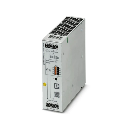
The Phoenix Contact QUINT4-ORING/12-24DC/2X10/2X10 redundancy module is engineered to deliver maximum reliability in industrial power systems. Supporting a 12–24 V DC input and two 10 A channels, it ensures secure decoupling of connected power supplies while actively monitoring their performance. With its innovative Auto Current Balancing (ACB) technology, the module equalizes load distribution, significantly extending the lifespan of redundant systems. Integrated surge protection and continuous redundancy monitoring provide stable power even in critical environments, reducing downtime and improving system availability where uninterrupted operation is essential.
Designed for demanding industrial applications, the QUINT4-ORING redundancy module enhances system stability through active decoupling with MOSFET technology. By balancing power supplies evenly, it minimizes component wear and effectively doubles service life, lowering maintenance and replacement costs. Users benefit from fast fault diagnostics through LED indicators and relay signaling, while high efficiency up to 99% ensures energy savings. Its compact DIN rail design allows seamless integration into existing panels, making it ideal for automation, machinery safety, and mission-critical control systems. The result is reliable, continuous power that keeps operations running smoothly under any condition.
Why Phoenix Contact QUINT4-ORING/12-24DC/2X10/2X10?
The QUINT4-ORING/12-24DC/2X10/2X10 stands out for its intelligent Auto Current Balancing (ACB) technology, which maximizes the lifespan of power supplies by distributing loads evenly. It offers not just redundancy, but active monitoring and fault detection, ensuring your critical systems never face unexpected downtime. Compact, efficient, and designed for tough industrial demands, it combines reliability, energy savings, and system longevity in one solution.
This redundancy module tackles one of the biggest challenges in automation and industrial operations: unplanned downtime due to power failure. By actively decoupling and monitoring power supplies, it guarantees continuous operation even if one source fails. Surge protection and high efficiency reduce risks of costly interruptions, while clear signaling simplifies troubleshooting. The result is a stable, dependable power infrastructure that protects processes, equipment, and productivity.
| Feature | Details | Benefit |
|---|---|---|
| Input Voltage Range | 12–24 V DC (operational range 8–29.5 V DC) | Flexible use in various DC applications |
| Nominal Current | 2x 10 A (Static Boost: 2x 12.5 A, Dynamic Boost: 2x 20 A for 5s) | Handles peak loads without disruption |
| Redundancy Technology | Active MOSFET decoupling with Auto Current Balancing (ACB) | Doubles power supply lifespan, ensures stable load sharing |
| Efficiency | Up to 99% at 24 V DC | Lower energy losses and reduced operating costs |
| Surge & Overvoltage Protection | Integrated protection up to 32 V DC | Safeguards connected equipment against failures |
| Monitoring & Diagnostics | LED indicators and relay outputs (Redundancy OK, ACB OK, DC OK) | Real-time system status, quick troubleshooting |
| Life Expectancy | >1 million hours MTBF at 25 °C | Long service life reduces replacement costs |
| Environmental Range | -40 °C to +70 °C, up to 5000 m altitude | Reliable performance in extreme conditions |
| Mounting Type | Compact DIN rail design (39 x 130 x 132 mm) | Saves cabinet space and allows easy integration |
| Certifications | UL, ATEX, IECEx, DNV, CE | Meets global safety and industry standards |
| Degree of Protection | IP20, metal housing with V0 flame rating | Durable construction for industrial environments |
| Weight | 320 g (without packaging) | Lightweight yet robust for control cabinets |
Download QUINT4-ORING/12-24DC/2X10/2X10 1088206 Datasheet
| Commercial Attribute | Details |
|---|---|
| GTIN (EAN/UPC) | 4055626887395 |
| Customs Tariff Number (HS Code) | 85371091 |
| Weight (incl. packing) | 597 g |
| Weight (net, excl. packing) | 320 g |
| Country of Origin | China (CN) |
In refinery environments, process control systems must never lose power, as interruptions can trigger safety hazards and production losses. The QUINT4-ORING redundancy module ensures that if one power supply fails, the second immediately maintains operation without any voltage drop. Its MOSFET decoupling provides efficient switching, while Auto Current Balancing reduces stress on each supply. This keeps PLCs, sensors, and critical controllers running continuously, avoiding downtime in one of the most demanding industrial settings.
Hydropower facilities rely on stable power for governor controllers, excitation systems, and monitoring equipment. Even short interruptions can compromise stability and safety. By using the QUINT4-ORING module, operators achieve continuous power through seamless redundancy. Its active current balancing prevents uneven load distribution, extending equipment life in harsh environments. Built-in monitoring and fault signaling further allow quick detection of issues, ensuring that renewable energy generation remains uninterrupted and secure under variable operating conditions.
Modern automotive factories operate around the clock, where robotic assembly lines depend on consistent low-voltage DC power. A brief power failure can cause machinery shutdowns, costly downtime, and safety risks. The QUINT4-ORING module prevents this by isolating faulty power supplies and guaranteeing stable voltage to PLCs and controllers. Its compact DIN-rail design makes it easy to integrate into control cabinets, while LED signaling provides immediate diagnostics. This allows automotive manufacturers to maintain production efficiency and worker safety.
Food production lines require frequent cleaning cycles, where equipment must restart seamlessly afterward. The QUINT4-ORING redundancy module ensures control systems and drives regain stable power immediately once operations resume. Surge protection shields sensitive electronics from voltage spikes during power restoration, while continuous monitoring enables quick troubleshooting in case of irregularities. This reliability minimizes downtime in hygienic environments, keeping production consistent while meeting strict safety and quality standards in food and beverage manufacturing.
| Category | Model / Name | Article Number | How It Relates / Benefit |
|---|---|---|---|
| Redundancy Module | QUINT4-ORING/24DC/2X40/2X40 | 2908760 | Higher current version (2×40 A) for larger systems needing expanded redundancy. |
| Power Supply | QUINT4-PS/1AC/24DC/20 | 2904601 | QUINT4 24 V DC, 20 A power supply designed to pair with redundancy modules. |
| Mounting Adapter | UTA 107/30 | 2320089 | Universal DIN rail adapter for secure installation of the redundancy module. |
| Mounting Adapter | UWA 182/52 | 2938235 | Universal wall adapter for stable mounting under strong vibration environments. |
| Signal Cable Set | QUINT-SIGNAL-CABLE | 2901832 | Pre-assembled signal cable set for monitoring redundancy and alarm outputs. |
| Protective Cover | EMC Shielding Cover | 2909910 | Provides additional shielding in EMC-sensitive environments. |
| Fuse Protection | CB TM1-16 | 2838339 | Circuit breaker recommended for input protection of 16 A redundancy connections. |
| Monitoring Device | QUINT-DIODE/24DC/2X20 | 2902444 | Alternative diode module for simpler redundancy without active monitoring. |
For expert guidance before placing your order.
Warranty – 1-year warranty for your peace of mind.
Global Shipping – We ship worldwide with secure packaging and reliable delivery.
Technical Support – Contact us for professional after-sales technical assistance.