Inosaki – Your Trusted Phoenix Contact Distributor
Inosaki proudly stands as one of the largest distributors of Phoenix Contact products, offering a comprehensive range of terminal blocks, interface modules, power supplies, and relays.
Series Models: PT Series, ST Series, TB Series, UT Series, and UK Series, PTV Series, UKH Series, Micro Series.
Discover industry-leading Phoenix Contact power supplies, such as:
Get Your Phoenix Contact Catalog Today
Need detailed product information? Contact us at sales@inosaki.com to request your Phoenix Contact catalog.
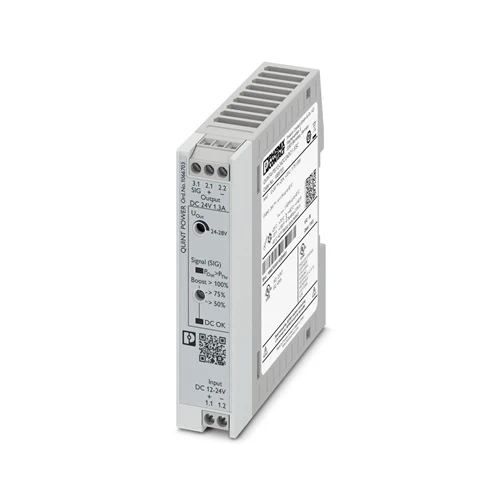
MINI DC/DC converter for MCR technology.
DC/DC converters alter the voltage level, regenerate the voltage at the end of long cables or enable the creation of independent supply systems by means of electrical isolation.
| Item number | 1066703 |
| Packing unit | 1 pc |
| Minimum order quantity | 1 pc |
| Product key | CMDI43 |
| GTIN | 4055626733692 |
| Weight per piece (including packing) | 227.6 g |
| Weight per piece (excluding packing) | 169 g |
| Customs tariff number | 85044095 |
| Country of origin | CN |
| Product type | DC/DC converters |
| Product family | QUINT POWER |
| MTBF (IEC 61709, SN 29500) | > 1999348 h (25 °C) |
| > 1120490 h (40 °C) | |
| > 471066 h (60 °C) | |
| Insulation characteristics | |
| Protection class | II |
| Degree of pollution | 2 |
| Life expectancy (electrolytic capacitors) | |
| Current | 0.65 A |
| Temperature | 40 °C |
| Time | 242000 h |
| Additional text | 24 V DC |
| Life expectancy (electrolytic capacitors) | |
| Current | 1.3 A |
| Temperature | 40 °C |
| Time | 160000 h |
| Additional text | 24 V DC |
| Life expectancy (electrolytic capacitors) | |
| Current | 1.3 A |
| Temperature | 30 °C |
| Time | 320000 h |
| Additional text | 24 V DC |
| Number of phases | 1.00 |
| Insulation voltage input/output | 2.6 kV DC (type test) |
| 1.2 kV DC (routine test) | |
| Switching frequency | 130.00 kHz … 130.00 kHz (Auxiliary converter stage) |
| 70.00 kHz … 250.00 kHz (Main converter stage) |
| Nominal input voltage range | 12 V DC … 24 V DC |
| Input voltage range | 12 V DC … 24 V DC -25 % … +33 % (SELV) |
| Wide-range input | yes |
| Electric strength, max. | 35 V DC (60 s) |
| Inrush current | typ. 1.6 A |
| Inrush current integral (I2t) | typ. 0.1 A2s |
| Inrush current limitation | typ. 1.6 A |
| Mains buffering time | typ. 19 ms (24 V DC) |
| Current consumption | typ. 3.75 A (12 V DC) |
| typ. 1.85 A (24 V DC) | |
| Typical response time | 700 ms (from SLEEP MODE) |
| Switch-on time | < 1 s |
| Input fuse | 15 A (fast blow, internal) |
| Recommended breaker for input protection | 10 A … 16 A (Characteristic B, C, D, K or comparable) |
| Efficiency | typ. 91.7 % (24 V DC) |
| Output characteristic | U/I Advanced |
| Nominal output voltage | 24 V DC |
| Setting range of the output voltage (USet) | 24 V DC … 28 V DC (> 24 V DC, constant capacity) |
| Nominal output current (IN) | 1.3 A |
| Static Boost (IStat.Boost) | 1.625 A (≤ 40 °C) |
| Dynamic Boost (IDyn.Boost) | 2.6 A (≤ 60 °C (4.9 s)) |
| Short-circuit-proof | yes |
| No-load proof | yes |
| Derating | > 60 °C (2.5%/K of POut nom.) |
| Output power (PN) | 30 W |
| Output power (PStat. Boost) | 38 W |
| Output power (PDyn. Boost) | 60 W |
| Feedback voltage resistance | ≤ 35 V DC |
| Protection against overvoltage at the output (OVP) | < 32 V DC |
| Residual ripple | < 20 mVPP |
| Control deviation static | < 1 % (change in load, static 10 % … 90 %) |
| Control deviation dynamic | < 1 % (change in load, static 10 % … 90 %) |
| Control deviation Input voltage change | < 1 % (change in load, static 10 % … 90 %) |
| Rise time | < 1 s (UOUT (10 % … 90 %)) |
| Connection in series | yes |
| Maximum no-load power dissipation | < 1.3 W |
| Power loss nominal load max. | < 8 W |
| Connection in parallel | yes, for redundancy and increased capacity |
| Input | |
| Position | 1.x |
| Conductor connection | |
| Connection method | Screw connection |
| rigid | 0.5 mm² … 2.5 mm² |
| flexible | 0.5 mm² … 2.5 mm² |
| flexible with ferrule without plastic sleeve | 0.5 mm² … 2.5 mm² |
| flexible with ferrule with plastic sleeve | 0.5 mm² … 2.5 mm² |
| rigid (AWG) | 22 … 14 |
| Stripping length | 8 mm |
| Tightening torque | 0.5 Nm … 0.6 Nm |
| Drive form screw head | Slotted L |
| Output | |
| Position | 2.x |
| Conductor connection | |
| Connection method | Screw connection |
| rigid | 0.2 mm² … 2.5 mm² |
| flexible | 0.25 mm² … 2.5 mm² |
| flexible with ferrule without plastic sleeve | 0.25 mm² … 2.5 mm² |
| flexible with ferrule with plastic sleeve | 0.25 mm² … 2.5 mm² |
| rigid (AWG) | 24 … 14 |
| Stripping length | 8 mm |
| Tightening torque | 0.5 Nm … 0.6 Nm |
| Drive form screw head | Slotted L |
| Signal | |
| Position | 3.x |
| Conductor connection | |
| Connection method | Screw connection |
| rigid | 0.14 mm² … 2.5 mm² |
| flexible | 0.14 mm² … 2.5 mm² |
| flexible with ferrule without plastic sleeve | 0.25 mm² … 2.5 mm² |
| flexible with ferrule with plastic sleeve | 0.25 mm² … 2.5 mm² |
| rigid (AWG) | 26 … 14 |
| Stripping length | 8 mm |
| Tightening torque | 0.5 Nm … 0.6 Nm |
| Drive form screw head | Slotted L |
| LED signaling | |
| Signal threshold | > PThr (LED lights up yellow, output power > PThr, depending on the rotary selector switch setting) |
| > 0.9 x USet (LED lights up green) | |
| < 0.9 x USet (LED flashes green) | |
| Signal output Configurable | |
| Digital | 0 V DC |
| 24 V DC | |
| 22 mA | |
| Default | 24 V DC |
| 22 mA | |
| 24 V DC for UOut > 0.9 x USet | |
| Item dimensions | |
| Width | 22.5 mm |
| Height | 99 mm |
| Depth | 90 mm |
| Installation dimensions | |
| Installation distance right/left (active) | 15 mm / 15 mm (POut ≥50% ) |
| Installation distance right/left (passive) | 5 mm / 5 mm (POut ≥50% ) |
| Installation distance right/left (active, passive) | 0 mm / 0 mm (POut ≤50 %) |
| Installation distance top/bottom (active) | 30 mm / 30 mm (POut ≥50% ) |
| Installation distance top/bottom (passive) | 30 mm / 30 mm (POut ≥50% ) |
| Installation distance top/bottom (active, passive) | 30 mm / 30 mm (POut ≤50 %) |
| Flammability rating according to UL 94 (housing / terminal blocks) | V0 |
| Housing material | Plastic |
| Type of housing | Polycarbonate (PC), UL 94 V0 |
| Ambient conditions | |
| Degree of protection | IP20 |
| Ambient temperature (operation) | -25 °C … 70 °C (> 60 °C Derating: 2,5 %/K) |
| Ambient temperature (storage/transport) | -40 °C … 85 °C |
| Ambient temperature (start-up type tested) | -40 °C |
| Maximum altitude | ≤ 5000 m (> 2000 m, observe derating) |
| Climatic class | 3K3 (in acc. with EN 60721) |
| Max. permissible relative humidity (operation) | ≤ 95 % (at 25 °C, non-condensing) |
| Shock | 18 ms, 30g, in each space direction (according to IEC 60068-2-27) |
| Vibration (operation) | < 15 Hz, ±2.5 mm amplitude; 15 Hz … 100 Hz: 2.3 g 90 Min. (in accordance with IEC 60068-2-6) |
| Temp code | T4 (-25 … +70 °C; > 60 °C, Derating: 2,5 %/K) |
| Overvoltage category | |
| EN 61010-1 | II (≤ 5000 m) |
| Safety for measurement, control, and laboratory equipment | |
| Standard designation | Electrical safety (of control and regulation devices) |
| Standards/specifications | IEC 61010-1 |
| Protective extra-low voltage | |
| Standard designation | Protective extra-low voltage |
| Standards/specifications | IEC 61010-1 (SELV) |
| Mains voltage dips | |
| Standard designation | Mains variation/undervoltage |
| Standards/specifications | EN 61000-4-29 |
| UL | |
| Identification | UL Listed UL 61010-1 |
| UL | |
| Identification | UL Listed UL 61010-2-201 |
| UL | |
| Identification | UL 121201 & CSA C22.2 No. 213-17 Class I, Division 2, Groups A, B, C, D T4 (Hazardous Location) |
| CSA | |
| Identification | CAN/CSA C22.2 No. 61010-1-12 |
| CSA | |
| Identification | CAN/CSA C22.2 No. 61010-2-201:18 |
| SIQ | |
| Identification | CB scheme (IEC 61010-1, IEC 61010-2-201) |
| Shipbuilding | |
| Identification | DNV GL |
| Electromagnetic compatibility | Conformance with EMC Directive 2014/30/EU |
| EMC requirements for noise emission | EN 61000-6-3 |
| EN 61000-6-4 | |
| EMC requirements for noise immunity | EN 61000-6-1 |
| EN 61000-6-2 | |
| EMC requirements, power plant | EN 61850-3 |
| EN 61000-6-5 | |
| Conducted noise emission | |
| Standards/regulations | EN 55016 |
| EN 61000-6-3 (Class B) | |
| Noise emission | |
| Standards/regulations | Additional basic standard EN 61000-6-5 (immunity in power station), IEC/EN 61850-3 (energy supply) |
| Noise emission | |
| Standards/regulations | EN 55016 |
| EN 61000-6-3 (Class B) | |
| DNV GL conducted noise emissions | |
| DNV | Class B |
| Additional text | Bridge and deck area |
| DNV GL noise radiation | |
| DNV | Class B |
| Additional text | Bridge and deck area |
| Electrostatic discharge | |
| Standards/regulations | EN 61000-4-2 |
| Electrostatic discharge | |
| Contact discharge | 6 kV (Test Level 4) |
| Discharge in air | 8 kV (Test Level 3) |
| Comments | Criterion A |
| Electromagnetic HF field | |
| Standards/regulations | EN 61000-4-3 |
| Electromagnetic HF field | |
| Frequency range | 80 MHz … 1 GHz |
| Test field strength | 20 V/m (Test Level 3) |
| Frequency range | 1 GHz … 6 GHz |
| Test field strength | 10 V/m (Test Level 3) |
| Comments | Criterion A |
| Fast transients (burst) | |
| Standards/regulations | EN 61000-4-4 |
| Fast transients (burst) | |
| Input | 2 kV (Test Level 4 – asymmetrical) |
| Output | 2 kV (Test Level 4 – asymmetrical) |
| Signal | 2 kV (Test Level 4 – asymmetrical) |
| Comments | Criterion B |
| Surge voltage load (surge) | |
| Standards/regulations | EN 61000-4-5 |
| Surge voltage load (surge) | |
| Input | 0.5 kV (Test Level 3 – symmetrical) |
| 1 kV (Test Level 3 – asymmetrical) | |
| Output | 0.5 kV (Test Level 2 – symmetrical) |
| 1 kV (Test Level 1 – asymmetrical) | |
| Signal | 0.5 kV (Test Level 2 – symmetrical) |
| 1 kV (Test Level 1 – asymmetrical) | |
| Comments | Criterion B |
| Conducted interference | |
| Standards/regulations | EN 61000-4-6 |
| Conducted interference | |
| Input/output/signal | asymmetrical |
| Frequency range | 0.15 MHz … 80 MHz |
| Comments | Criterion A |
| Voltage | 10 V (Test Level 3) |
| Power frequency magnetic field | |
| Standards/regulations | EN 61000-4-8 |
| Frequency | 16.67 Hz |
| 50 Hz | |
| 60 Hz | |
| Test field strength | 100 A/m |
| Additional text | 60 s |
| Comments | Criterion A |
| Frequency | 50 Hz |
| 60 Hz | |
| Frequency range | 50 Hz … 60 Hz |
| Test field strength | 1 kA/m |
| Additional text | 3 s |
| Frequency | 0 Hz |
| Test field strength | 300 A/m |
| Additional text | DC, 60 s |
| Voltage dips | |
| Standards/regulations | EN 61000-4-29 |
| Voltage | 24 V DC |
| Voltage dip | 70 % |
| Number of periods | 0.5 / 1 / 25 periods |
| Time | 100 ms |
| Additional text | Test Level 2 |
| Comments | Criterion A |
| Voltage dip | 40 % |
| Number of periods | 5 / 10 / 50 periods |
| Time | 100 ms |
| Additional text | Test Level 2 |
| Comments | Criterion A |
| Voltage dip | 0 % |
| Number of periods | 0.5 / 1 / 5 / 50 periods |
| Time | 50 ms |
| Additional text | Test Level 2 |
| Comments | Criterion B |
| Pulse-shape magnetic field | |
| Standards/regulations | EN 61000-4-9 |
| Test field strength | 1000 A/m |
| Comments | Criterion A |
| Asymmetrical conducted disturbance variables | |
| Standards/regulations | EN 61000-4-16 |
| Test level 1 | 15 Hz 150 Hz (Test Level 3) |
| Voltage | 10 V 1 V (Permanent) |
| Test level 2 | 150 Hz 1.5 kHz (Test Level 3) |
| Voltage | 1 V |
| Test level 3 | 1.5 kHz 15 kHz (Test Level 3) |
| Voltage | 1 V 10 V |
| Test level 4 | 15 kHz 150 kHz (Test Level 3) |
| Voltage | 10 V |
| Test level 5 | 16.7 Hz 50 Hz 60 Hz 150 Hz 180 Hz (Test Level 3) |
| Voltage | 10 V (Permanent) |
| Test level 6 | 0 Hz 16.7 Hz 50 Hz 60 Hz (Test Level 3) |
| Voltage | 100 V (1 s) |
| Comments | Criterion A |
| Alternating component of direct voltage | |
| Standards/regulations | EN 61000-4-17 |
| Alternating component | 10 % (UN) |
| Frequency | 50 Hz |
| 100 Hz | |
| 150 Hz | |
| 300 Hz | |
| Comments | Criterion A |
| Attenuated oscillating wave | |
| Standards/regulations | EN 61000-4-18 |
| Input, output (test level 1) | 1 MHz (Test Level 2 – symmetrical) |
| Voltage | 0.5 kV |
| Input, output (test level 2) | 1 MHz (Test Level 2 – asymmetrical) |
| Voltage | 1 kV |
| Signals (test level 1) | 1 MHz (Test Level 2 – symmetrical) |
| Voltage | 0.5 kV |
| Signals (test level 2) | 1 MHz (Test Level 2 – asymmetrical) |
| Voltage | 1 kV |
| Comments | Criterion A |
| Attenuated oscillating magnetic field | |
| Standards/regulations | EN 61000-4-10 |
| Test field strength | 100 A/m |
| Test level 1 | 100 kHz |
| Test field strength | 100 A/m |
| Test level 2 | 1 MHz |
| Comments | Criterion A |
| Criteria | |
| Criterion A | Normal operating behavior within the specified limits. |
| Criterion B | Temporary impairment to operational behavior that is corrected by the device itself. |
| Criterion C | Temporary adverse effects on the operating behavior, which the device corrects automatically or which can be restored by actuating the operating elements. |
| Mounting type | DIN rail mounting |
| Assembly note | alignable: PN ≥50%, 5 mm horizontally, 15 mm next to active components, 50 mm vertically alignable: PN <50%, 0 mm horizontally, 40 mm vertically top, 20 mm vertically bottom |
| With protective coating | no |