Inosaki – Your Trusted Phoenix Contact Distributor
Inosaki proudly stands as one of the largest distributors of Phoenix Contact products, offering a comprehensive range of terminal blocks, interface modules, power supplies, and relays.
Series Models: PT Series, ST Series, TB Series, UT Series, and UK Series, PTV Series, UKH Series, Micro Series.
Discover industry-leading Phoenix Contact power supplies, such as:
Get Your Phoenix Contact Catalog Today
Need detailed product information? Contact us at sales@inosaki.com to request your Phoenix Contact catalog.
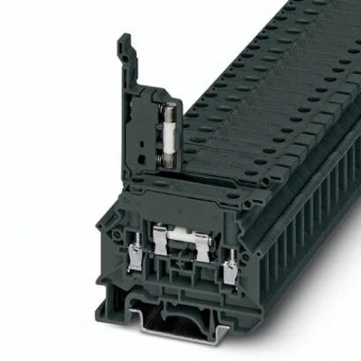
Fuse terminal block, connection method: Screw connection, cross section: 0.5 mm²- 6 mm², AWG: 20 – 10, nominal current: 6.3 A, nom. voltage: 500 V, width: 8.2 mm, fuse type: G / 5 x 20, mounting type: NS 35/7,5, NS 35/15, NS 32, color: dark gray
| Article Number | 3246418 |
|---|---|
| Number of levels | 1 |
| Number of connections | 2 |
| Nominal cross section | 4 mm² |
| Color | dark gray |
| Insulating material | PA |
| Flammability rating according to UL 94 | V0 |
| Rated surge voltage | 6 kV |
| Degree of pollution | 3 |
| Overvoltage category | III |
| Insulating material group | I |
| Connection in acc. with standard | IEC 60947-7-3 |
| Maximum load current | 6.3 A (the current is determined by the fuse used) |
| Nominal current IN | 6.3 A (the current is determined by the fuse used) |
| Nominal voltage UN | 500 V (the voltage is determined by the light indicator.) |
| Fuse | G / 5 x 20 |
| Open side panel | Yes |
| Shock protection test specification | DIN EN 50274 (VDE 0660-514):2002-11 |
| Back of the hand protection | guaranteed |
| Finger protection | guaranteed |
| Note | Only with closed clamping unit |
| Result of surge voltage test | Test passed |
| Surge voltage test setpoint | 4.8 kV |
| Note | The current is determined by the fuse used, the voltage by the fuse or selected light indicator. |
| Result of power-frequency withstand voltage test | Test passed |
| Power frequency withstand voltage setpoint | 1.5 kV |
| Note | The current is determined by the fuse used, the voltage by the fuse or selected light indicator. |
| Result of tight fit on support | Test passed |
| Contact resistance | Test passed |
| Compatibitity between modular fuse terminal block and fuse insert | Test passed |
| Actuatiing forces on plug in or lever in fuse insert carriers | Test passed |
| Result of the test for mechanical stability of terminal points (5 x conductor connection) | Test passed |
| Result of flexion and pull-out test | Test passed |
| Bending test rotation speed | 10 rpm |
| Bending test turns | 135 |
| Bending test conductor cross section/weight | 0.5 mm² / 0.3 kg |
| 4 mm² / 0.9 kg | |
| 6 mm² / 1.4 kg | |
| Testing the rated value of the power dissipation (overload and short circuit Protection) | Test passed |
| Testing the rated value of the power dissipation (exclusively short circuit protection) | Test passed |
| Result of temperature-rise test | Test passed |
| Result of thermal test | Test passed |
| Oscillation, broadband noise test result | Test passed |
| Test specification, oscillation, broadband noise | DIN EN 50155 (VDE 0115-200):2008-03 |
| Test spectrum | Service life test category 1, class B, body mounted |
| Test frequency | f1 = 5 Hz to f2 = 150 Hz |
| ASD level | 1.857 (m/s²)²/Hz |
| Acceleration | 0.8g |
| Test duration per axis | 5 h |
| Test directions | X-, Y- and Z-axis |
| Shock test result | Test passed |
| Test specification, shock test | DIN EN 50155 (VDE 0115-200):2008-03 |
| Shock form | Half-sine |
| Acceleration | 5g |
| Shock duration | 30 ms |
| Number of shocks per direction | 3 |
| Test directions | X-, Y- and Z-axis (pos. and neg.) |
| Relative insulation material temperature index (Elec., UL 746 B) | 130 °C |
| Temperature index of insulation material (DIN EN 60216-1 (VDE 0304-21)) | 130 °C |
| Static insulating material application in cold | -60 °C |
| Width | 8.2 mm |
|---|---|
| Length | 58 mm |
| Height NS 35/7,5 | 48 mm |
| Height NS 35/15 | 55.5 mm |
| Height NS 32 | 53 mm |
| Conductor cross section solid min. | 0.5 mm² |
|---|---|
| Conductor cross section solid max. | 6 mm² |
| Conductor cross section flexible min. | 0.5 mm² |
| Conductor cross section flexible max. | 4 mm² |
| Conductor cross section AWG min. | 20 |
| Conductor cross section AWG max. | 10 |
| Conductor cross section flexible, with ferrule without plastic sleeve min. | 0.5 mm² |
| Conductor cross section flexible, with ferrule without plastic sleeve max. | 4 mm² |
| Conductor cross section flexible, with ferrule with plastic sleeve min. | 0.5 mm² |
| Conductor cross section flexible, with ferrule with plastic sleeve max. | 2.5 mm² |
| Cross section with insertion bridge solid min. | 0.5 mm² |
| Cross section with insertion bridge, solid max. | 4 mm² |
| Cross section with insertion bridge stranded min. | 0.5 mm² |
| Cross section with insertion bridge, stranded max. | 4 mm² |
| Cross section with insertion bridge stranded, with ferrule without plastic sleeve min. | 0.5 mm² |
| Cross section with insertion bridge stranded, with ferrule without plastic sleeve max. | 2.5 mm² |
| Cross section with insertion bridge stranded, with ferrule without plastic sleeve min. | 0.5 mm² |
| Cross section with insertion bridge stranded, with ferrule with plastic sleeve max. | 1.5 mm² |
| 2 conductors with same cross section, solid min. | 0.5 mm² |
| 2 conductors with same cross section, solid max. | 1.5 mm² |
| 2 conductors with same cross section, stranded min. | 0.5 mm² |
| 2 conductors with same cross section, stranded max. | 1.5 mm² |
| Two conductors with the same cross section stranded, with ferrule and without plastic sleeve, minimum | 0.5 mm² |
| Two conductors with the same cross section stranded, with ferrule and without plastic sleeve, maximum | 1.5 mm² |
| Two conductors with the same cross section, flexible, with TWIN ferrules, with plastic sleeve, minimum | 0.5 mm² |
| Two conductors with the same cross section, flexible, with TWIN ferrules, with plastic sleeve, maximum | 1.5 mm² |
| Cross section with insertion bridge, solid max. | 4 mm² |
| Cross section with insertion bridge, stranded max. | 4 mm² |
| Connection method | Screw connection |
| Stripping length | 9 mm |
| Screw thread | M3 |
| Tightening torque, min | 0.5 Nm |
| Tightening torque max | 0.6 Nm |
| Operating temperature | -60 °C … 105 °C (max. short-term operating temperature 130°C) |
|---|---|
| Ambient temperature (storage/transport) | -25 °C … 60 °C (for a short time, not exceeding 24 h, -60 °C to +70 °C) |
| Permissible humidity (storage/transport) | 30 % … 70 % |
| Ambient temperature (assembly) | -5 °C … 70 °C |
| Ambient temperature (actuation) | -5 °C … 70 °C |
| Connection in acc. with standard | UL |
|---|---|
| IEC 60947-7-3 | |
| Flammability rating according to UL 94 | V0 |
| China RoHS | Environmentally friendly use period: unlimited = EFUP-e |
|---|---|
| No hazardous substances above threshold values |