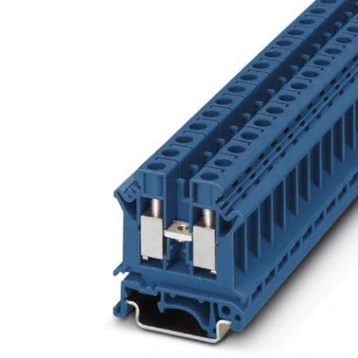
Feed-through terminal block, nom. voltage: 800 V, nominal current: 57 A, connection method: Screw connection, number of connections: 2, cross section: 0.5 mm² – 16 mm², AWG: 20 – 6, width: 10.2 mm, color: blue, mounting type: NS 35/7,5, NS 35/15, NS 32
General
| Article Number |
3005086 |
| Number of levels |
1 |
| Number of connections |
2 |
| Potentials |
1 |
| Nominal cross section |
10 mm² |
| Color |
blue |
| Insulating material |
PA |
| Flammability rating according to UL 94 |
V0 |
| Mounting type |
NS 35/7,5 |
| Rated surge voltage |
8 kV |
| Degree of pollution |
3 |
| Overvoltage category |
III |
| Insulating material group |
I |
| Maximum load current |
76 A (with 16 mm² conductor cross section) |
| Nominal current IN |
57 A |
| Nominal voltage UN |
800 V |
| Open side panel |
Yes |
| Shock protection test specification |
IEC 60529:2001-02 |
| Back of the hand protection |
guaranteed |
| Finger protection |
guaranteed |
| Result of surge voltage test |
Test passed |
| Result of power-frequency withstand voltage test |
Test passed |
| Power frequency withstand voltage setpoint |
2 kV |
| Result of the test for mechanical stability of terminal points (5 x conductor connection) |
Test passed |
| Result of flexion and pull-out test |
Test passed |
| Bending test rotation speed |
10 rpm |
| Bending test turns |
135 |
| Bending test conductor cross section/weight |
0.5 mm² / 0.3 kg |
|
10 mm² / 2 kg |
| Tensile test result |
Test passed |
| Result of tight fit on support |
Test passed |
| Tight fit on carrier |
NS 32/NS 35 |
| Setpoint |
5 N |
| Result of voltage-drop test |
Test passed |
| Result of temperature-rise test |
Test passed |
| Requirement temperature-rise test |
Increase in temperature ≤ 45 K |
| Short circuit stability result |
Test passed |
| Conductor cross section short circuit testing |
10 mm² |
| Short-time current |
1.2 kA |
| Conductor cross section short circuit testing |
16 mm² |
| Short-time current |
1.92 kA |
| Result of thermal test |
Test passed |
| Proof of thermal characteristics (needle flame) effective duration |
30 s |
| Relative insulation material temperature index (Elec., UL 746 B) |
130 °C |
| Temperature index of insulation material (DIN EN 60216-1 (VDE 0304-21)) |
130 °C |
| Static insulating material application in cold |
-60 °C |
| Surface flammability NFPA 130 (ASTM E 162) |
passed |
| Specific optical density of smoke NFPA 130 (ASTM E 662) |
passed |
| Calorimetric heat release NFPA 130 (ASTM E 1354) |
28 MJ/kg |
| Smoke gas toxicity NFPA 130 (SMP 800C) |
passed |
| Fire protection for rail vehicles (DIN EN 45545-2) R22 |
HL 1 – HL 3 |
| Fire protection for rail vehicles (DIN EN 45545-2) R23 |
HL 1 – HL 3 |
| Fire protection for rail vehicles (DIN EN 45545-2) R24 |
HL 1 – HL 3 |
| Fire protection for rail vehicles (DIN EN 45545-2) R26 |
HL 1 – HL 3 |
Dimensions
| Width |
10.2 mm |
| End cover width |
1.8 mm |
| Length |
42.5 mm |
| Height NS 35/7,5 |
47.3 mm |
| Height NS 35/15 |
54.8 mm |
| Height NS 32 |
52.3 mm |
Connection data
| Connection method |
Screw connection |
| Screw thread |
M4 |
| Stripping length |
10 mm |
| Tightening torque, min |
1.5 Nm |
| Tightening torque max |
1.8 Nm |
| Connection in acc. with standard |
IEC 60947-7-1 |
| Conductor cross section solid min. |
0.5 mm² |
| Conductor cross section solid max. |
16 mm² |
| Conductor cross section AWG min. |
20 |
| Conductor cross section AWG max. |
6 |
| Conductor cross section flexible min. |
0.5 mm² |
| Conductor cross section flexible max. |
10 mm² |
| Min. AWG conductor cross section, flexible |
20 |
| Max. AWG conductor cross section, flexible |
8 |
| Conductor cross section flexible, with ferrule without plastic sleeve min. |
0.5 mm² |
| Conductor cross section flexible, with ferrule without plastic sleeve max. |
10 mm² |
| Conductor cross section flexible, with ferrule with plastic sleeve min. |
0.5 mm² |
| Conductor cross section flexible, with ferrule with plastic sleeve max. |
6 mm² |
| Cross section with insertion bridge, solid max. |
10 mm² |
| Cross section with insertion bridge, stranded max. |
10 mm² |
| 2 conductors with same cross section, solid min. |
0.5 mm² |
| 2 conductors with same cross section, solid max. |
4 mm² |
| 2 conductors with same cross section, stranded min. |
0.5 mm² |
| 2 conductors with same cross section, stranded max. |
4 mm² |
| Two conductors with the same cross section, flexible, with TWIN ferrules, with plastic sleeve, minimum |
0.5 mm² |
| Two conductors with the same cross section, flexible, with TWIN ferrules, with plastic sleeve, maximum |
6 mm² |
| Two conductors with the same cross section stranded, with ferrule and without plastic sleeve, minimum |
0.5 mm² |
| Two conductors with the same cross section stranded, with ferrule and without plastic sleeve, maximum |
2.5 mm² |
| Internal cylindrical gage |
B6 |
Ambient conditions
| Operating temperature |
-60 °C … 105 °C (max. short-term operating temperature 130°C) |
| Ambient temperature (storage/transport) |
-25 °C … 60 °C (for a short time, not exceeding 24 h, -60 °C to +70 °C) |
| Permissible humidity (storage/transport) |
30 % … 70 % |
| Ambient temperature (assembly) |
-5 °C … 70 °C |
| Ambient temperature (actuation) |
-5 °C … 70 °C |
Standards and Regulations
| Connection in acc. with standard |
CSA |
|
IEC 60947-7-1 |
| Flammability rating according to UL 94 |
V0 |
Environmental Product Compliance
| REACh SVHC |
Lead 7439-92-1 |
| China RoHS |
Environmentally Friendly Use Period = 50 years |
|
For details about hazardous substances go to tab “Downloads”, Category “Manufacturer’s declaration” |