Inosaki – Your Trusted Phoenix Contact Distributor
Inosaki proudly stands as one of the largest distributors of Phoenix Contact products, offering a comprehensive range of terminal blocks, interface modules, power supplies, and relays.
Our Best-Selling Terminal Blocks: Feed-Through, Fuse Modular, Spring Cage, Double Level, Multi-Level
Series Models: PT Series, ST Series, TB Series, UT Series, and UK Series, PTV Series, UKH Series, Micro Series.
Reliable Power Supply Solutions
Discover industry-leading Phoenix Contact power supplies, such as:
- QUINT Power – Premium performance for critical systems
- STEP Power – Compact design for space-saving applications
- Trio Power – Rugged and reliable for industrial needs
- UNO Power – Cost-effective and efficient
Get Your Phoenix Contact Catalog Today
Need detailed product information? Contact us at sales@inosaki.com to request your Phoenix Contact catalog.
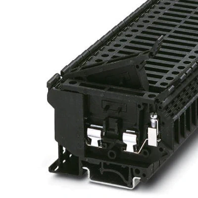
Fuse modular terminal block, fuse type: Glass / ceramics / …, number of positions: 1, connection method: Screw connection, cross section: 0.2 mm²- 4 mm², AWG: 24 – 12, nominal current: 6.3 A, nom. voltage: 800 V, width: 8.2 mm, fuse type: G / 5 x 20 / 5 x 25 / 5 x 30, mounting type: NS 35/7,5, NS 35/15, NS 32, color: black
General
| Note |
For terminal marking, please use marking material with 8.2 mm pitch. |
|
For lever marking, please use marking material with 6.2 mm pitch. |
| Article Number |
3004100 |
| Number of levels |
1 |
| Number of connections |
2 |
| Nominal cross section |
4 mm² |
| Color |
black |
| Insulating material |
PA |
| Flammability rating according to UL 94 |
V0 |
| Rated surge voltage |
8 kV |
| Rated operating voltage |
250 V |
| Degree of pollution |
3 |
| Overvoltage category |
III |
| Insulating material group |
I |
| Connection in acc. with standard |
IEC 60947-7-3 |
| Maximum load current |
6.3 A (the current is determined by the fuse used) |
| Nominal current IN |
6.3 A |
| Nominal voltage UN |
800 V (As a fuse terminal block) |
| Fuse |
G / 5 x 20 / 5 x 25 / 5 x 30 |
| Fuse type |
Glass / ceramics / … |
| Open side panel |
No |
| Number of positions |
1 |
| Shock protection test specification |
DIN EN 50274 (VDE 0660-514):2002-11 |
| Back of the hand protection |
guaranteed |
| Finger protection |
guaranteed |
| Note |
Swing the locking lever to its final position before replacing the fuse. |
| Result of surge voltage test |
Test passed |
| Surge voltage test setpoint |
9.8 kV |
| Result of power-frequency withstand voltage test |
Test passed |
| Power frequency withstand voltage setpoint |
2 kV |
| Result of tight fit on support |
Test passed |
| Contact resistance |
Test passed |
| Compatibitity between modular fuse terminal block and fuse insert |
Test passed |
| Actuatiing forces on plug in or lever in fuse insert carriers |
Test passed |
| Result of the test for mechanical stability of terminal points (5 x conductor connection) |
Test passed |
| Result of flexion and pull-out test |
Test passed |
| Bending test rotation speed |
10 rpm |
| Bending test turns |
135 |
| Bending test conductor cross section/weight |
0.2 mm² / 0.2 kg |
|
4 mm² / 0.9 kg |
| Testing the rated value of the power dissipation (overload and short circuit Protection) |
Test passed |
| Testing the rated value of the power dissipation (exclusively short circuit protection) |
Test passed |
| Result of temperature-rise test |
Test passed |
| Result of thermal test |
Test passed |
| Oscillation, broadband noise test result |
Test passed |
| Test specification, oscillation, broadband noise |
DIN EN 50155 (VDE 0115-200):2008-03 |
| Test spectrum |
Service life test category 1, class B, body mounted |
| Test frequency |
f1 = 5 Hz to f2 = 150 Hz |
| ASD level |
1.857 (m/s²)²/Hz |
| Acceleration |
0.8g |
| Test duration per axis |
5 h |
| Test directions |
X-, Y- and Z-axis |
| Shock test result |
Test passed |
| Test specification, shock test |
DIN EN 50155 (VDE 0115-200):2008-03 |
| Shock form |
Half-sine |
| Acceleration |
5g |
| Shock duration |
30 ms |
| Number of shocks per direction |
3 |
| Test directions |
X-, Y- and Z-axis (pos. and neg.) |
| Relative insulation material temperature index (Elec., UL 746 B) |
130 °C |
| Temperature index of insulation material (DIN EN 60216-1 (VDE 0304-21)) |
125 °C |
| Static insulating material application in cold |
-60 °C |
| Surface flammability NFPA 130 (ASTM E 162) |
passed |
| Specific optical density of smoke NFPA 130 (ASTM E 662) |
passed |
| Smoke gas toxicity NFPA 130 (SMP 800C) |
passed |
| Calorimetric heat release NFPA 130 (ASTM E 1354) |
27,5 MJ/kg |
| Fire protection for rail vehicles (DIN EN 45545-2) R22 |
HL 1 – HL 3 |
| Fire protection for rail vehicles (DIN EN 45545-2) R23 |
HL 1 – HL 3 |
| Fire protection for rail vehicles (DIN EN 45545-2) R24 |
HL 1 – HL 3 |
| Fire protection for rail vehicles (DIN EN 45545-2) R26 |
HL 1 – HL 3 |
Dimensions
| Width |
8.2 mm |
| Length |
72.5 mm |
| Height NS 35/7,5 |
56.5 mm |
| Height NS 35/15 |
64 mm |
| Height NS 32 |
61.5 mm |
Connection data
| Conductor cross section solid min. |
0.2 mm² |
| Conductor cross section solid max. |
4 mm² |
| Conductor cross section flexible min. |
0.2 mm² |
| Conductor cross section flexible max. |
4 mm² |
| Conductor cross section AWG min. |
24 |
| Conductor cross section AWG max. |
12 |
| Conductor cross section flexible, with ferrule without plastic sleeve min. |
0.25 mm² |
| Conductor cross section flexible, with ferrule without plastic sleeve max. |
4 mm² |
| Conductor cross section flexible, with ferrule with plastic sleeve min. |
0.25 mm² |
| Conductor cross section flexible, with ferrule with plastic sleeve max. |
4 mm² |
| Cross section with insertion bridge, solid max. |
4 mm² |
| Cross section with insertion bridge, stranded max. |
4 mm² |
| 2 conductors with same cross section, solid min. |
0.2 mm² |
| 2 conductors with same cross section, solid max. |
1.5 mm² |
| 2 conductors with same cross section, stranded min. |
0.2 mm² |
| 2 conductors with same cross section, stranded max. |
1.5 mm² |
| Two conductors with the same cross section stranded, with ferrule and without plastic sleeve, minimum |
0.25 mm² |
| Two conductors with the same cross section stranded, with ferrule and without plastic sleeve, maximum |
1.5 mm² |
| Two conductors with the same cross section, flexible, with TWIN ferrules, with plastic sleeve, minimum |
0.5 mm² |
| Two conductors with the same cross section, flexible, with TWIN ferrules, with plastic sleeve, maximum |
1.5 mm² |
| Cross section with insertion bridge, solid max. |
4 mm² |
| Cross section with insertion bridge, stranded max. |
4 mm² |
| Connection method |
Screw connection |
| Stripping length |
8 mm |
| Internal cylindrical gage |
A4 |
| Screw thread |
M3 |
| Tightening torque, min |
0.6 Nm |
| Tightening torque max |
0.8 Nm |
Ambient conditions
| Operating temperature |
-60 °C … 105 °C (max. short-term operating temperature 125°C) |
| Ambient temperature (storage/transport) |
-25 °C … 60 °C (for a short time, not exceeding 24 h, -60 °C to +70 °C) |
| Permissible humidity (storage/transport) |
30 % … 70 % |
| Ambient temperature (assembly) |
-5 °C … 70 °C |
| Ambient temperature (actuation) |
-5 °C … 70 °C |
Standards and Regulations
| Connection in acc. with standard |
CSA |
|
IEC 60947-7-3 |
| Flammability rating according to UL 94 |
V0 |
Environmental Product Compliance
| China RoHS |
Environmentally Friendly Use Period = 50 years |
|
For details about hazardous substances go to tab “Downloads”, Category “Manufacturer’s declaration” |