Inosaki – Your Trusted Phoenix Contact Distributor
Inosaki proudly stands as one of the largest distributors of Phoenix Contact products, offering a comprehensive range of terminal blocks, interface modules, power supplies, and relays.
Series Models: PT Series, ST Series, TB Series, UT Series, and UK Series, PTV Series, UKH Series, Micro Series.
Discover industry-leading Phoenix Contact power supplies, such as:
Get Your Phoenix Contact Catalog Today
Need detailed product information? Contact us at sales@inosaki.com to request your Phoenix Contact catalog.
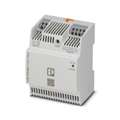
STEP POWER power supplies for distribution boards. The STEP POWER power supplies with Push-in connection technology are the professional solution for intelligent building automation. The compact devices are economical, space-saving, and flexible in application.
| Width | 72 mm |
|---|---|
| Height | 90 mm |
| Depth | 61 mm |
| 55 mm (Device depth (DIN rail mounting)) | |
| Horizontal pitch | 4 Div. (DIN 43880) |
| Installation distance right/left | 0 mm / 0 mm |
| Installation distance top/bottom | 30 mm / 30 mm |
| Ambient temperature (operation) | -10 °C … 70 °C (Derating: > 50 °C; 2 %/K) |
|---|---|
| Ambient temperature (start-up type tested) | -25 °C |
| Ambient temperature (storage/transport) | -40 °C … 85 °C |
| Max. permissible relative humidity (operation) | ≤ 95 % (at 25 °C, non-condensing) |
| Maximum altitude | ≤ 4000 m (> 2000 m, Derating: 10 %/1000 m) |
| Degree of pollution | 2 |
| Input voltage range | 100 V AC … 240 V AC -15 % … +10 % |
|---|---|
| 110 V DC … 250 V DC -20 % … +40 % | |
| Derating | < 100 V AC … 85 V AC (1 %/V) |
| < 110 V DC … 88 V DC (1 %/V) | |
| Frequency range (fN) | 50 Hz … 60 Hz ±10 % |
| Typical national grid voltage | 120 V AC |
| 230 V AC | |
| Voltage type of supply voltage | AC/DC |
| Current consumption | 1.07 A (100 V AC) |
| 0.47 A (240 V AC) | |
| 0.97 A (110 V DC) | |
| 0.41 A (250 V DC) | |
| Discharge current to PE | < 0.25 mA |
| Mains buffering time | typ. 20 ms (120 V AC) |
| typ. 20 ms (230 V AC) | |
| Switch-on time | typ. 2 s |
| Inrush current | typ. 37 A |
| Inrush current integral (I2t) | typ. 0.4 A2s |
| Type of protection | Transient surge protection |
| Protective circuit/component | Varistor |
| Device mains fuse | 4 A internal (device protection), slow-blow |
| Recommended breaker for input protection | 6 A … 16 A (Characteristics B, C, D, K) |
| Nominal output voltage | 24 V DC |
|---|---|
| Setting range of the output voltage (USet) | 22 V DC … 27 V DC (> 24 V DC, constant capacity restricted) |
| Nominal output current (IN) | 4 A |
| Control deviation | < 0.5 % (Static load change 10 % … 90 %) |
| < 3 % (Dynamic load change 10 % … 90 %, (10 Hz)) | |
| < 0.1 % (change in input voltage ±10 %) | |
| Short-circuit-proof | yes |
| No-load proof | yes |
| Residual ripple | typ. 150 mVPP |
| Connection in parallel | yes, for increasing power and redundancy with diode |
| Connection in series | yes, for increased output voltage |
| Feedback voltage resistance | ≤ 35 V DC |
| Protection against overvoltage at the output (OVP) | < 35 V DC |
| Rise time | typ. 100 ms (UOut = 10 % … 90 %) |
| Derating | > 50 °C … 70 °C (2 % / K) |
| Crest factor | typ. 1.74 |
| typ. 2.08 | |
| Minimum no-load power dissipation | < 0.21 W (120 V AC) |
| Maximum power dissipation in no-load condition | < 0.21 W (230 V AC) |
| Minimum nominal load power dissipation | < 7 W (120 V AC) |
| Power loss nominal load max. | < 5.7 W (230 V AC) |
| Article Number | 1140066 |
|---|---|
| Net weight | 255 g |
| Environmental protection directive | RoHS Directive 2011/65/EU |
| WEEE | |
| Reach | |
| Efficiency | > 93 % (120 V AC) |
| > 94 % (230 V AC) | |
| MTBF (IEC 61709, SN 29500) | > 1350000 h (25 °C) |
| > 750000 h (40 °C) | |
| > 488000 h (50 °C) | |
| Insulation voltage input/output | 4 kV AC (type test) |
| 3.75 kV AC (routine test) | |
| Degree of protection | IP20 |
| Protection class | II (in closed control cabinet) |
| Efficiency Level | VI |
| Housing material | Polycarbonate |
| Foot latch material | Polyamid |
| Mounting position | horizontal DIN rail NS 35, EN 60715 |
| Assembly instructions | alignable: 0 mm horizontally, 30 mm vertically |
| Connection method | Push-in connection |
|---|---|
| Stripping length | 10 mm |
| Conductor cross section solid | 0.2 mm² … 2.5 mm² |
| Conductor cross section flexible | 0.2 mm² … 2.5 mm² |
| Flexible conductor cross section (ferrule with plastic sleeve) | 0.2 mm² … 1 mm² |
| Flexible conductor cross section flexible (ferrule, w/o plastic sleeve) | 0.5 mm² … 2.5 mm² |
| Conductor cross section AWG | 24 … 14 (Cu) |
| Types of signaling | LED |
|---|---|
| UOut | > 0,9 x UN (UN = 24 V DC) (LED lights up green) |
| < 0,9 x UN (UN = 24 V DC) (LED off) |
| Standard designation | Electrical safety |
|---|---|
| Standards/regulations | IEC 61010-1 (SELV) |
| Standard designation | Protective extra-low voltage |
| Standards/regulations | IEC 61010-1 (SELV) |
| IEC 61010-2-201 (PELV) | |
| Standard designation | Safe isolation |
| Standards/regulations | IEC 61558-2-16 |
| Standard designation | Low-voltage power supplies, DC output |
| Standards/regulations | EN 61204-3 |
| Standard designation | Safety requirements for electrical equipment for measurement, control, and laboratory use |
| Standards/regulations | IEC 61010-1 |
| Standard designation | Safety of electrical devices for household use and similar purposes |
| Standards/regulations | DIN EN 60335-1 |
| Overvoltage category EN 61010-1 | II (≤ 4000 m) |
| Overvoltage category EN 62477-1 | III (≤ 2000 m) |
| Designation | UL |
|---|---|
| Identification | UL/C-UL Listed UL 61010-1 |
| Designation | UL |
| Identification | UL/C-UL Listed UL 61010-2-201 |
| Designation | UL |
| Identification | UL/C-UL Listed ANSI/UL 121201 Class I, Division 2, Groups A, B, C, D (Hazardous Location) |
| Electromagnetic compatibility | Conformance with EMC Directive 2014/30/EU |
|---|---|
| Low Voltage Directive | Conformance with Low Voltage Directive 2014/35/EC |
| Conducted noise emission | EN 55016 |
| EN 61000-6-3 (Class B) | |
| Noise emission | EN 55016 |
| EN 61000-6-3 (Class B) | |
| Harmonic currents | EN 61000-3-2 |
| EN 61000-3-2 (Class A) | |
| Flicker | EN 61000-3-3 |
| Electrostatic discharge | EN 61000-4-2 |
| Contact discharge | 6 kV (Test Level 3) |
| Discharge in air | 8 kV (Test Level 3) |
| Electromagnetic HF field | EN 61000-4-3 |
| Frequency range | 80 MHz … 1 GHz |
| Test field strength | 10 V/m (Test Level 3) |
| Frequency range | 1 GHz … 6 GHz |
| Test field strength | 10 V/m (Test Level 3) |
| Comments | Criterion A |
| Fast transients (burst) | EN 61000-4-4 |
| Input | asymmetrical 4 kV (Test Level 4) |
| Output | asymmetrical 2 kV (Test Level 3) |
| Comments | Criterion A |
| Surge voltage load (surge) | EN 61000-4-5 |
| Input | symmetrical 2 kV (Test Level 4) |
| asymmetrical 4 kV (Test Level 4) | |
| Output | symmetrical 1 kV (Test Level 3) |
| asymmetrical 2 kV (Test Level 3) | |
| Comments | Criterion A |
| Conducted interference | EN 61000-4-6 |
| Frequency range | 0.15 MHz … 80 MHz |
| Voltage | 10 V (Test Level 3) |
| Comments | Criterion A |
| Voltage dips | EN 61000-4-11 |
| Voltage | 230 V AC |
| Frequency | 50 Hz |
| Voltage dip | 70 % |
| Number of periods | 25 periods |
| Additional text | Class 3 |
| Comments | Criterion A |
| Voltage dip | 40 % |
| Number of periods | 10 periods |
| Additional text | Class 3 |
| Comments | Criterion B |
| Voltage dip | 0 % |
| Number of periods | 1 period |
| Additional text | Class 3 |
| Comments | Criterion A |
| Criterion A | Normal operating behavior within the specified limits. |
| Criterion B | Temporary impairment to operational behavior that is corrected by the device itself. |
| Criterion C | Temporary adverse effects on the operating behavior, which the device corrects automatically or which can be restored by actuating the operating elements. |
| REACh SVHC | Lead 7439-92-1 |
|---|